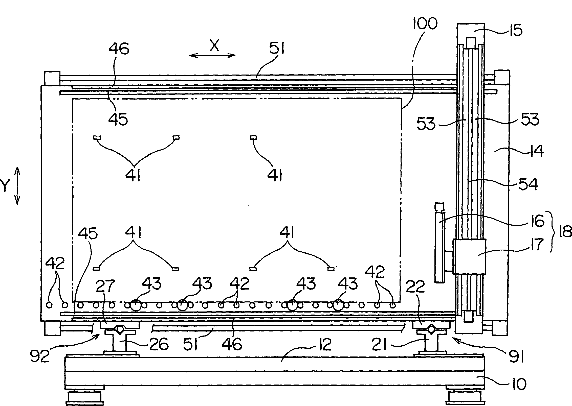
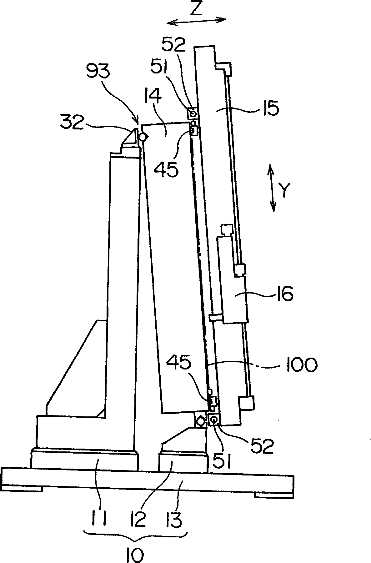
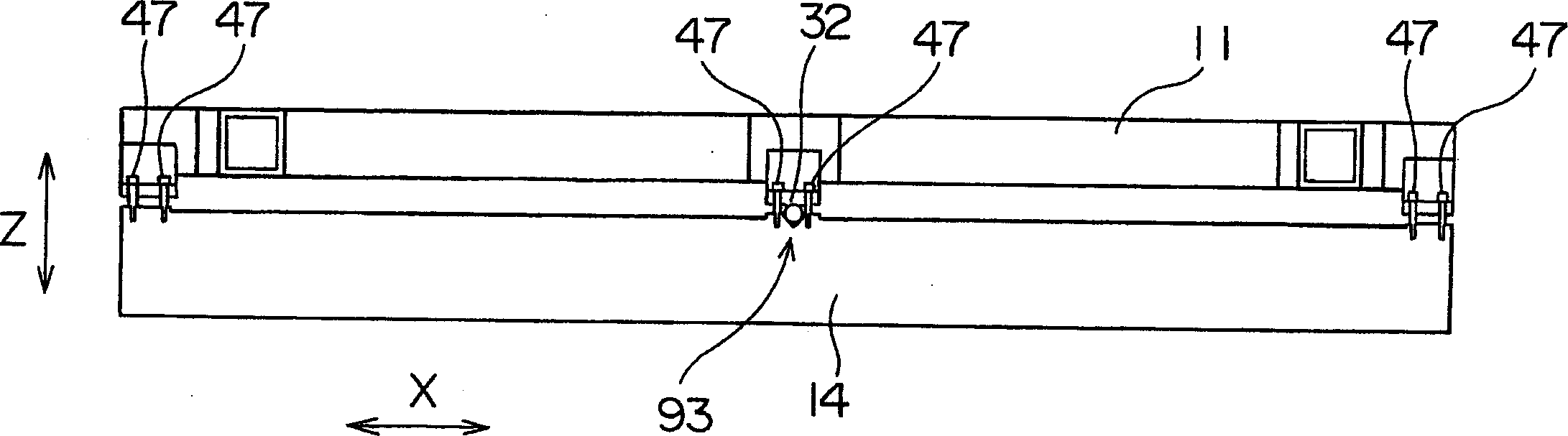
[0031] Hereinafter, embodiments of the present invention will be described based on the drawings. figure 1 It is a front view of the length gauge as the substrate measuring device according to the present invention, figure 2 Is its side view, image 3 It is its top view. In addition, in image 3 Only the main parts of the first supporting member 11 and the stage portion 15 are shown in the, and other members are omitted.
[0032] The length measuring instrument has: a base 10 composed of a first support member 11, a second support member 12, and a base member 13; a stage portion 14 supported by the base 10; along the surface of the stage portion 14 A gantry 15 that can move in the left-right direction; an imaging unit 18 that is composed of a photographing unit 16 and a moving member 17 that are connected to each other and can move in the up-and-down direction along the gantry 15.
[0033] In addition, in this manual, as from Figure 1 to Figure 3 As shown, a three-dimensional coordinate system with the surface of the stage 14 as the X and Y directions is set, and the left and right directions along the surface of the stage 14 are set as the X direction. The vertical direction is referred to as the Y direction, and the direction perpendicular to the surface of the stage portion 14 is referred to as the Z direction. In addition, in the specification, the X direction is referred to as the left-right direction, and the Y direction is referred to as the up-down direction as necessary.
[0034] The base 10 has: a first support portion 91 that supports the stage portion 14 in a state of restricting movement of the stage portion 14 in the X, Y, and Z directions relative to the base 10; and a second support portion 92 , Which supports the stage portion 14 in a state of restricting the movement of the stage portion 14 in the Y and Z directions with respect to the base 10; the third support portion 93 restricts the stage with respect to the base 10 The state of the movement of the part 14 in the Z direction supports the stage part 14. The stage portion 14 is supported by the base 10 in a state where the surface thereof is inclined at a slight angle with respect to the vertical direction.
[0035] Figure 4A~Figure 4C It is an explanatory view showing the first support portion 91, the second support portion 92, and the third support portion 93. Reference figure 1 as well as Figure 4A , An abutting metal fitting 21 is arranged on the upper right side of the second support member 12 of the base 10. The abutting metal fitting 21 is formed with a conical recess 24 having a V-shaped cross section. In addition, a contact metal fitting 22 is arranged at the lower right side of the stage part 14. The contact metal fitting 22 is also formed with a conical recess 25 having a V-shaped cross section. Furthermore, a steel ball 23 is arranged between these recesses 24 and 25. Therefore, the stage portion 14 mounted on the base 10 due to its own weight is supported by the support portion 91 in a state where the movement of the stage portion 14 in the X, Y, and Z directions relative to the base 10 is restricted. With.
[0036] Reference figure 1 as well as Figure 4B , An abutting metal fitting 26 is arranged on the upper left side of the second support member 12 of the base 10. A conical recess 29 having a V-shaped cross section is formed in the contact metal fitting 26. In addition, a contact metal fitting 27 is arranged at the lower left side of the stage portion 14. The contact metal fitting 27 is formed with a substantially semi-cylindrical recess 31 having a substantially U-shaped cross section. Furthermore, a steel ball 28 is arranged between these recesses 29 and 31. Therefore, the stage portion 14 mounted on the base 10 due to its own weight is in a state where the stage portion 14 can move relative to the base 10 in the X direction but restricts movement in the Y and Z directions through the support portion 92 Was supported.
[0037] Reference figure 2 , image 3 as well as Figure 4C As shown, abutting metal fittings 32 are arranged on the upper center of the first support member 11 of the base 10. The surface of the contact metal fitting 32 facing the stage portion 14 is a flat surface. In addition, a conical recess 34 having a V-shaped cross section is formed in the upper center of the back side of the stage portion 14. Furthermore, a steel ball 33 is arranged between the flat surface of the abutting metal fitting 32 and the recess 34. Therefore, the stage portion 14 leaning on the side of the first support member 11 due to its own weight allows the stage portion 14 to move relative to the base 10 in the X and Y directions through the support portion 93, but the movement in the Z direction is restricted. The state is supported.
[0038] In addition, such as image 3 As shown, the top of the stage part 14 is provided with a tipping prevention bolt 47 for preventing the stage part 14 from falling forward for some reason. In addition, a drop prevention bolt (not shown) is also provided in the same manner, so that the stage portion 14 does not fall off from the first support portion 91 and the second support portion 92.
[0039] That is, the above-mentioned fall prevention bolt 47 allows the stage portion 14 to move slightly in the X and Y directions, as long as the stage portion 14 is restricted so as not to be separated from the base 10 by a predetermined distance or more so that the steel ball 33 does not Just leave the recess 24. In addition, instead of the falling prevention bolt, for example, a chain or a steel wire may be used to connect the stage portion 14 and the base 10.
[0040] The stage portion 14 is supported by the first support portion 91, the second support portion 92, and the third support portion 93 having such a structure, so that the stage portion 14 does not receive stress from the base 10, and It is supported by the base 10 in a state where the surface is inclined at a slight angle with respect to the vertical direction. Here, the so-called "not subject to stress from the base" means that due to the above-mentioned structure, even if the base 10 or the stage portion 14 is deformed due to the difference in expansion and contraction rate caused by temperature changes, for example, In this case, the stage part 14 does not receive stress due to deformation from the base 10 either. In other words, the stage portion 14 is supported in a state of being movable only a small distance relative to the base 10, so that even if the stage portion 14 is deformed or changed in size due to temperature or gravity, etc., it can be allowed This variation (the variation can be absorbed).
[0041] In addition, considering the stability of the support, the position of the support portion 93 may be a predetermined distance upward from the support portions 91, 92 at the lower end of the support substrate 100, and the ideal position is at the upper end of the stage portion 14. Near the center of the side. However, for example, the support portion 93 may be divided to the left and right sides of the stage portion 14 to arrange two or more points, and the stage portion 14 may be supported by the two or more points. However, considering that when a plurality of support portions 93 are used, the position of each support portion 93 will vary in the Z direction. Therefore, it is preferable to provide a Z direction position adjustment mechanism on the support portion 93, such as a position to abut the metal fitting 32. Adjust institutions, etc.
[0042] In addition, the support portion 91 adopts a method of restricting movement in the XYZ direction, but may have a structure such that the stage portion 14 is not separated from the base 10, similarly to the support portion 92, in the X The direction can be supported by small movements. In addition, two or more support portions 92 may be provided to support the lower end of the stage portion 14 at three or more points. As such a modified example, for example, the stage part 14 may be mounted on the base 10 formed on the guide rail so as to be able to move slightly in the X direction. Of course, it is difficult in terms of mechanical accuracy to support the lower end of the stage part 14 in a state of uniform contact with the guide rail. Therefore, when deformation due to mechanical accuracy becomes a problem, as in the above embodiment, as long as the support part The lower end of the stage portion 14 may be supported by a plurality of defined points like 91 and 92.
[0043] Also, refer to Figure 1 to Figure 3 , On the surface of the stage portion 14 are arranged: 7 guide rollers 41, which abut against the back of the substrate 100 and guide the substrate 100; a plurality of guide rollers 42, which abut and guide the lower end of the substrate 100 The substrate 100.
[0044] Figure 5 It is an explanatory diagram showing the relationship between the substrate 100 and the guide rollers 41 and 42.
[0045] The guide roller 41 is arranged at a position where its outer peripheral surface only partially protrudes from the surface of the stage portion 14. In addition, the guide roller 42 is arranged at a position capable of supporting the lower end of the substrate 100. A recess 44 for reliably supporting the lower end of the substrate 100 is formed on the guide roller 42. By a driving mechanism not shown, these guide rollers 41 can be Figure 5 The guide position of the substrate 100 indicated by the solid line in the Figure 5 Move between the evacuation positions indicated by dotted lines.
[0046] Also, refer to figure 1 On the surface of the stage portion 14, four lifting rollers 43 that abut the lower end of the substrate 100 and lift the substrate 100 are arranged. The lifting roller 43 has a structure that is raised and lowered between a standby position and a supporting position. The standby position is a position where the upper end of the lifting roller 43 is arranged below the upper end of the guide roller 42, and the supporting position is a position where the upper end of the lifting roller 43 is arranged The position above the upper end of the guide roller 42. In addition, a plurality of suction holes (not shown) are formed on the surface of the stage portion 14.
[0047] When the substrate 100 is loaded on the stage portion 14, the guide rollers 41 and 42 are arranged in the state where the lift roller 43 is arranged in the standby position Figure 5 The guide position of the substrate 100 is indicated by a solid line in the middle, and the substrate 100 is guided by these guide rollers 41 and 42. Next, the lifting roller 43 is raised to the supporting position. As a result, the substrate 100 originally supported by the guide roller 42 becomes supported by the lift roller 43. In this state, the guide roller 41 is arranged at Figure 5 At the same time as the guide position of the substrate 100 indicated by the dotted line in the center, air is sucked through the suction hole formed on the surface of the stage portion 14. Thereby, the substrate 100 is sucked and held on the stage portion 14 in a state where the lower end portion is supported by the lift roller 43.
[0048] The guide roller 42 and the lifting roller 43 constitute a substrate supporting member of the present invention for supporting the lower end of the substrate 100.
[0049] A pair of guide rails 45 extending in the X direction are arranged on the surface of the stage portion 14. The gantry 15 is guided by the guide rail 45 so that it can reciprocate in the X direction. In addition, on the surface of the stage portion 14, a pair of linear scales 46 are arranged in parallel with the pair of guide rails 45. The position of the gantry 15 in the X direction is measured by a pair of linear scales 46. In addition, the reason for providing a pair of linear scales 46 is to correct the yaw error of the gantry 15.
[0050] Such as figure 1 as well as figure 2 As shown, stators 51 of linear motors are arranged at the upper and lower ends of the stage portion 14. In addition, such as figure 2 As shown, a pair of movers 52 are provided on the back of the frame 15. The gantry 52 is driven by a linear motor composed of these stators 51 and movers 52, and reciprocates in the X direction.
[0051] Such as figure 1 As shown, a pair of guide rails 53 extending in the Y direction are arranged on the surface of the stand 15. The moving member 17 of the imaging unit 18 is guided by the guide rail 53 together with the imaging unit 16 to be able to reciprocate in the Y direction. In addition, on the stand 15, a linear scale (not shown) is arranged in parallel with the pair of guide rails 53. The position of the imaging unit 18 in the Y direction is measured by this linear scale.
[0052] The stator 54 of the linear motor is arranged on the surface of the frame 15. In addition, a mover is arranged on the back of the moving member 17 of the imaging unit 18. The imaging unit 18 is driven by the linear motor composed of the stator 54 and the mover, and reciprocates in the Y direction.
[0053] Figure 6 It is a schematic diagram of the photographing unit 16.
[0054] The imaging unit 16 uses a high-magnification CCD camera 61 or a low-magnification CCD camera 62 to capture an image of the substrate 100 irradiated by coaxial reflection illumination.
[0055] That is, the light emitted from the light source 63 passes through the pair of lenses 64 and is reflected by the half lens 65, and then irradiates the substrate 100 sucked and held on the surface of the stage portion 14 via the objective lens 66. Then, the light reflected by the surface of the substrate 100 passes through the objective lens 66 and the half lens 65, is reflected by the reflection mirror 67, and enters the half lens 68. Half of the light rays incident on the half lens 68 pass through the half lens 68 and pass through the magnifying optical system 69 before being incident on the CCD camera 61. On the other hand, the remaining half of the light rays incident on the half lens 68 are reflected by the half lens 68, and then reflected by the mirror 71, and then incident on the CCD camera 62.
[0056] When measuring the length of the pattern of the substrate 100 by the length measuring instrument having such a structure, the imaging unit 16 captures two points on the substrate 100 while the substrate is sucked and held on the stage portion 14. Then, the movement amount of the imaging unit 18 in the X direction is measured by the linear scale 46, and the movement amount of the imaging unit 18 in the Y direction is measured by the linear scale installed on the gantry 15 to calculate the distance between the two points.
[0057] At this time, the stage portion 14 does not receive stress from the base 10, but is supported by the base 10 with its surface inclined at a slight angle with respect to the vertical direction, and the stage 15 is supported by the stage portion that is not stressed. 14 is guided in the left and right directions, and the imaging unit 18 is moved in the vertical direction on the gantry 15. As a result, even in the case of a large substrate 100, it is possible to perform accurate execution while reducing the footprint of the device. Measurement of substrate 100.
[0058] In addition, in the above-described embodiment, a structure is adopted in which the light source 63 of the imaging unit 16 illuminates the substrate 100 and captures the reflected light on the surface of the substrate 100. However, it is also possible to adopt a structure in which the stage part 14 is made of a light-transmitting material, or an opening is formed in the center of the stage part 14 to capture light transmitted through the substrate 100.
[0059] In addition, in the above-mentioned embodiment, the present invention is applied to a length measuring instrument for measuring the distance between two points on the substrate 100, but the present invention is also applicable to other substrate measuring devices such as a substrate inspection device.