Insertion support system
A technology that supports systems and subjects, and is applied in medical science, surgery, diagnosis, etc., and can solve problems such as the inability to determine the navigation path from the starting point to the target area, and the unnavigable end point to be designated as this target area, etc.
- Summary
- Abstract
- Description
- Claims
- Application Information
AI Technical Summary
Problems solved by technology
Method used
Image
Examples
Embodiment 1
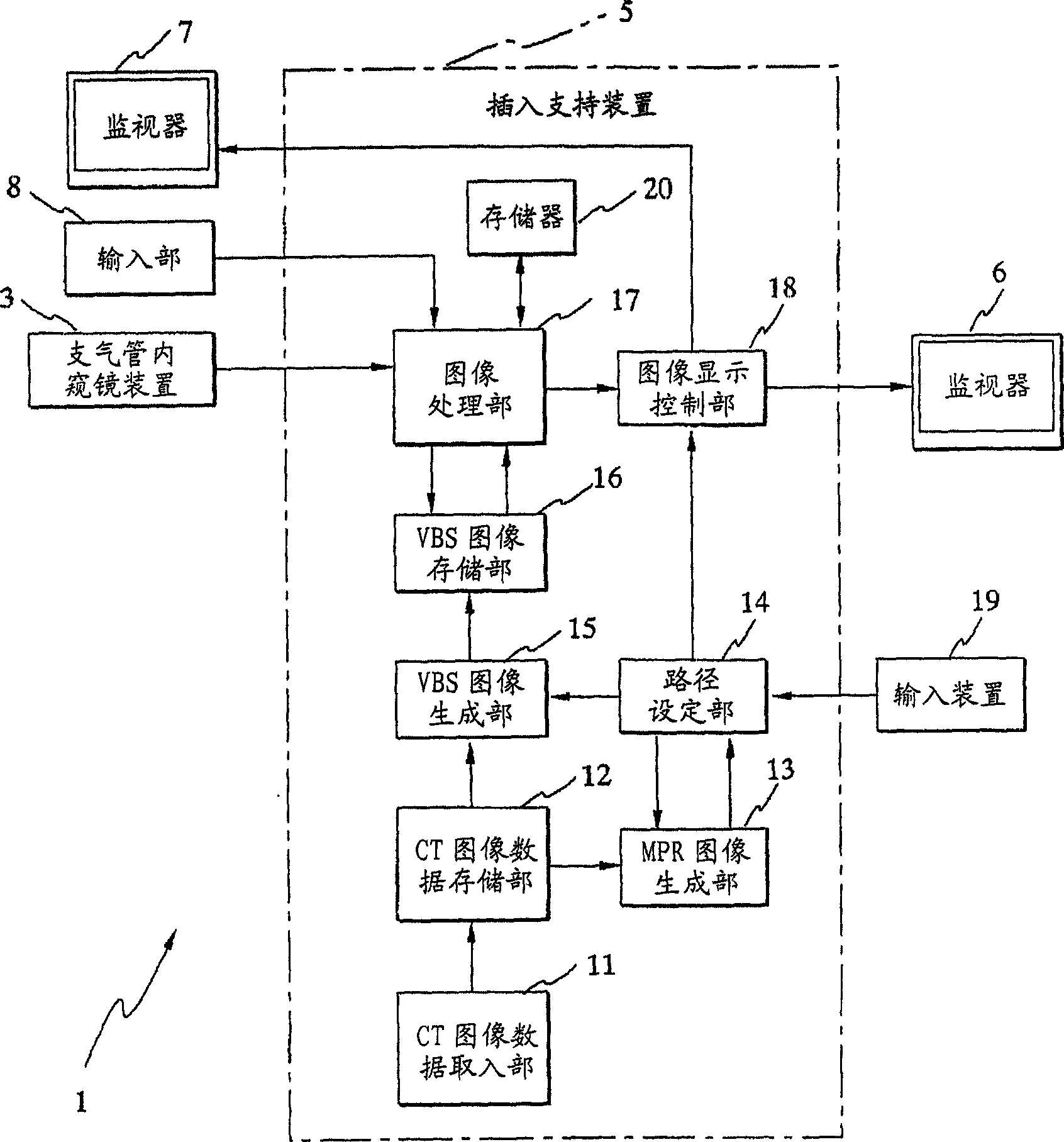
[0070] Such as figure 1 As shown, the bronchial insertion support system 1 of the first embodiment is composed of a bronchial endoscope device 3 and an insertion support device 5 .
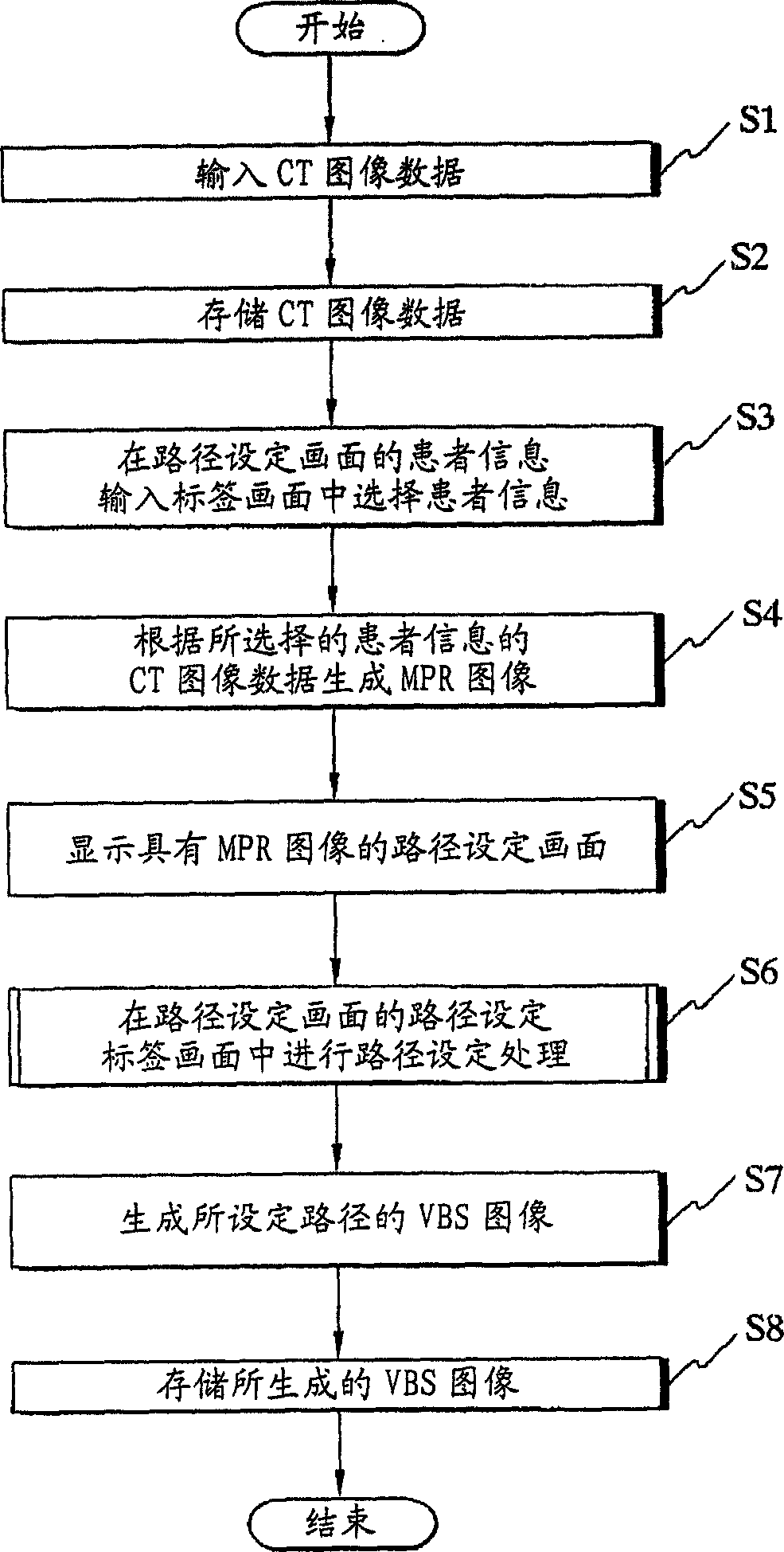
[0071] The insertion support device 5 generates a virtual endoscopic image (hereinafter referred to as a VBS image) of the inside of the bronchi based on the CT image data, and combines the endoscopic image (hereinafter referred to as a real-time image) obtained by the bronchial endoscope device 3 with the VBS image. The results are synthesized and displayed on the monitor 6, thereby supporting the insertion of the bronchial endoscope device 3 into the bronchi.
[0072] In addition, although not shown in the figure, the bronchoscope device 3 is composed of a bronchoscope having an imaging unit, a light source for supplying illumination light to the bronchoscope, and a camera control unit for signal processing the imaging signals from the bronchoscope, etc. A bronchoscope is inserted into the bron...
Embodiment 2
[0106] Such as Figure 19 As shown, the bronchial insertion support system 301 of the second embodiment is composed of a bronchial endoscope device 303 and an insertion support device 305 .
[0107] The insertion support device 305 generates a virtual internal video image (hereinafter referred to as a VBS image) of the inside of the bronchus based on the CT image data, and combines the endoscopic image (hereinafter referred to as a real-time image) obtained by the bronchial endoscope device 303 with the VBS image. The results are synthesized and displayed on the monitor 306, thereby supporting the insertion of the bronchoendoscopic device 303 into the bronchi.
[0108] In addition, although not shown, the bronchoendoscopic device 303 is composed of a bronchoscope having an imaging unit, a light source for supplying illumination light to the bronchoscope, and a camera control unit for performing signal processing on imaging signals from the bronchoscope, and the like. A bronch...
Embodiment 3
[0149] Such as Figure 39 As shown, the bronchial insertion support system 501 of the third embodiment is composed of a bronchial endoscope device 503 and an insertion support device 505 .
[0150] The insertion support device 505 generates a virtual endoscopic image (hereinafter referred to as a VBS image) of the inside of the bronchus based on the CT image data, and combines the endoscopic image (hereinafter referred to as a real-time image) obtained by the bronchial endoscope device 503 with the VBS image. The results are synthesized and displayed on the monitor 506 to support the insertion of the bronchoendoscopic device 503 into the bronchi.
[0151] In addition, although not shown in the figure, the bronchoscope device 503 is composed of a bronchoscope having an imaging unit, a light source for supplying illumination light to the bronchoscope, and a camera control unit for performing signal processing on imaging signals from the bronchoscope, and the like. A bronchoscop...
PUM
 Abstract
Description
Claims
Application Information
 - R&D
- Intellectual Property
- Life Sciences
- Materials
- Tech Scout
- Unparalleled Data Quality
- Higher Quality Content
- 60% Fewer Hallucinations
Browse by: Latest US Patents, China's latest patents, Technical Efficacy Thesaurus, Application Domain, Technology Topic, Popular Technical Reports.
© 2025 PatSnap. All rights reserved.Legal|Privacy policy|Modern Slavery Act Transparency Statement|Sitemap|About US| Contact US: help@patsnap.com


