

Shutter curtain lifting prevention structure in shutter device
A technology for rolling gates and door curtains, which is applied to door/window protection devices, windows/doors, building components, etc. It can solve problems such as inability to switch, inability to ensure the prevention effect, and inability to prevent the lifting of the gate, so as to achieve the effect of preventing lifting
- Summary
- Abstract
- Description
- Claims
- Application Information
AI Technical Summary
Problems solved by technology
Method used
Image

Examples
Embodiment 1
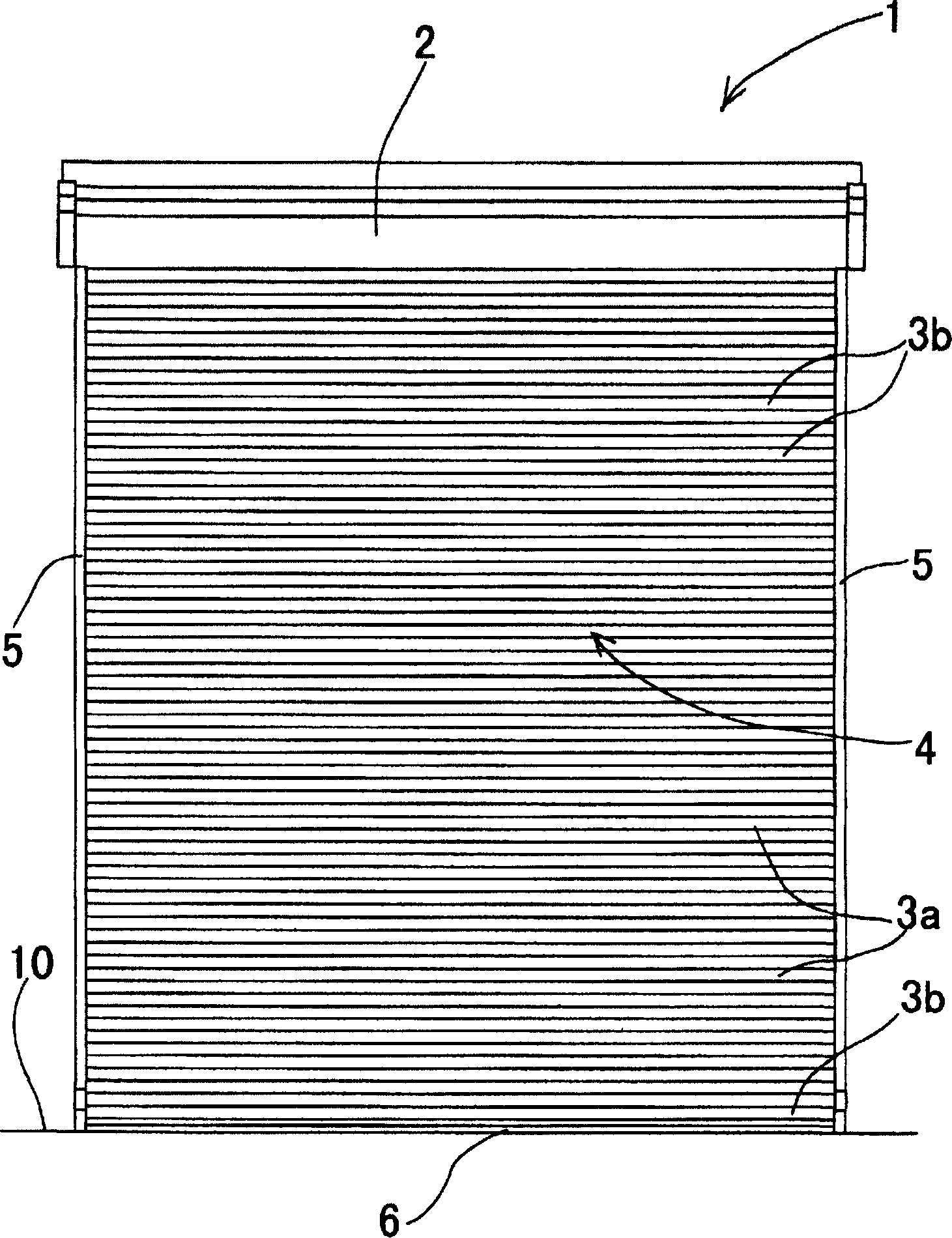
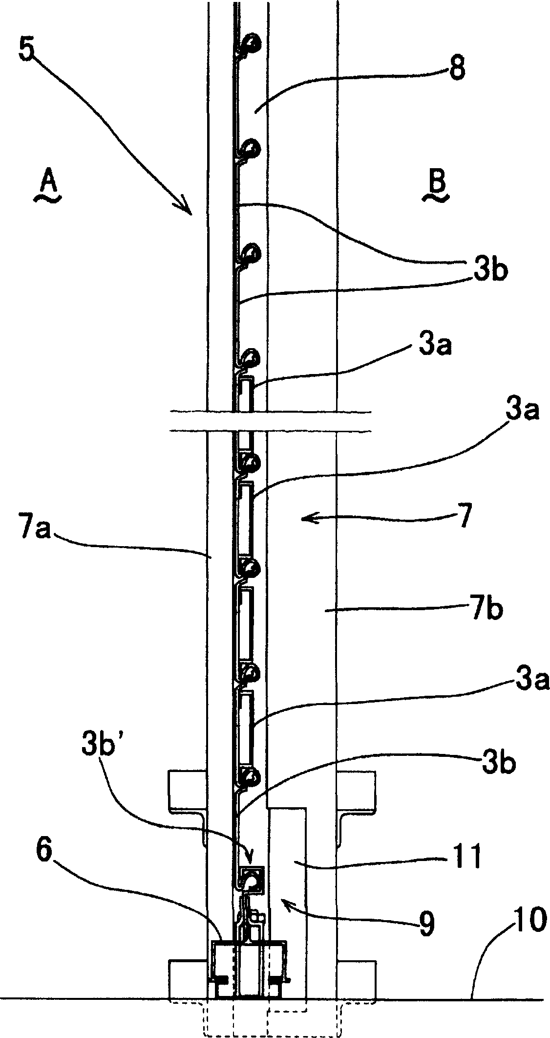
[0097] Embodiments of the present invention will be described in detail based on the drawings. figure 1 Among them, 1 is a rolling shutter device installed at the opening of the building. The rolling shutter device 1 is structured as follows. On a reel (not shown) in the shutter box 2 provided at the upper part of the opening, the rolling shutter device is wound in the vertical direction. The gate curtain 4 formed by flexibly connecting a plurality of slats 3a, 3a... and 3b, 3b... has front surfaces 7, 7 separated from and facing the guide rails 5, 5 erected on the left and right sides of the opening of the building. The two ends of the gate curtain 4 are embedded in the guide groove 8 formed on the top, and the opening of the building is opened and closed. The lower limit switch is switched to a locking action, thereby stopping the repeated rotation of the reel. At the same time, the free rotation of the reel is braked by a braking mechanism not shown, and the suspended gate ...
Embodiment 2
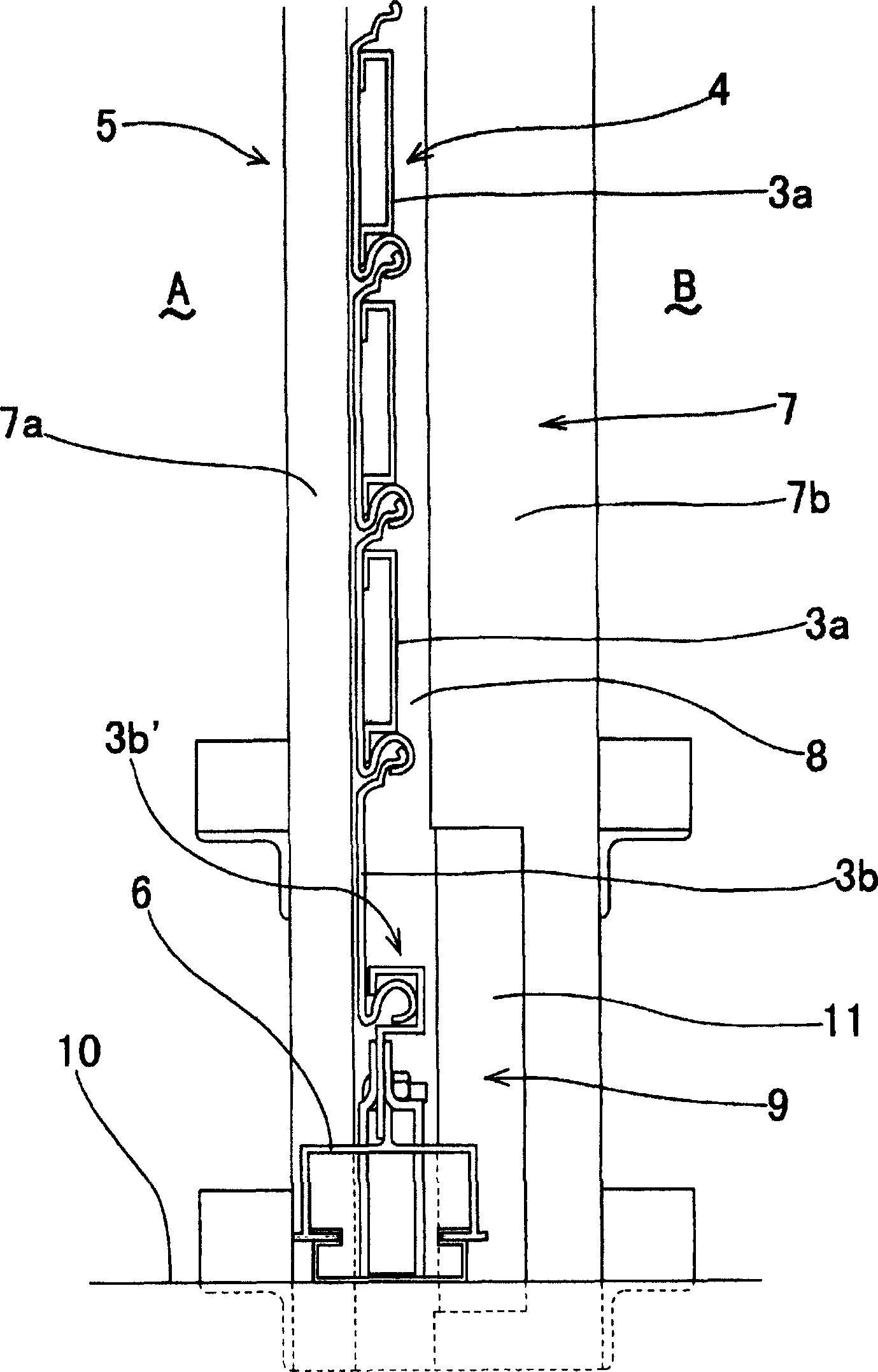
[0106] Next, in the above-mentioned Embodiment 1, the cover body 11 is formed from an elastically deformable metal plate such that the front end surface 11d of the front end side excess length portion 11c is in contact with the inner surface of the roof inner sheet 5b provided on the guide rail 5. The detection switch 12 is contacted to detect the lifting of the seat plate 6, but it can also be the following structure, as shown in Figure 7 (a), by bending the plastically deformed metal plate into the same shape as the above-mentioned embodiment 1, the cover body 11 is formed ', the detection part 12' is arranged inside it, as shown in figure (b), when the above-mentioned cover body 11' is pressed against the interlocking part 3b' of the slat 3b located directly above the seat plate 6, the cover body is used 11' presses and deforms the detection part 12' toward the plastic deformation of the inner side B of the house, and detects that the seat plate 6 of the gate curtain 4 that ...
Embodiment 3
[0109] refer to Figure 8 Example 3 will be described. Figure 8 on the left with image 3 correspond, Figure 8 The right picture of Figure 6 Correspondingly, the same reference numerals are used for the same constituent elements, and the above description can be referred to for the constituent elements with the same reference numerals. Figure 8 The figure on the left is a figure showing the lower end of the shutter curtain with the opening fully closed. A guide groove 8 of the guide rail 5 is formed between the roof outer surface 7 a and the roof inner surface 7 b constituting the front surface of the guide rail 5 .
[0110] On the inner side surface 7b, an inner side notch recess 90 is formed upward from a portion located on the upper end side of the seat plate 6 of the shutter curtain 4 in a fully closed state, and the horizontal upper end edge 900 of the inner side notch recess 90 constitutes snap part. In the fully closed state, the lower end edge 901 of the insi...
PUM
 Abstract
Description
Claims
Application Information