Check patentability & draft patents in minutes with Patsnap Eureka AI!

Multifunctional numerical control machine

A CNC machine tool, multi-functional technology, applied in the direction of metal processing mechanical parts, clamping, support, etc., can solve the problems of inability to meet mass production, high production cost, high price, etc., to achieve a wide range of processing, high production efficiency, manufacturing low cost effect

Inactive Publication Date: 2006-12-13
应圣平 +1
View PDF0 Cites 12 Cited by
  • Summary
  • Abstract
  • Description
  • Claims
  • Application Information

AI Technical Summary

Problems solved by technology

[0002] At present, if the various processes of machining shaft parts such as arc groove processing, linear groove processing, hole processing, chamfering and boss processing, etc. are to be completed on the same metal cutting machine tool, only CNC milling machines or CNC milling machines can be used. Machining center equipment, while CNC milling

Method used


Image

  • Multifunctional numerical control machine
  • Multifunctional numerical control machine

Examples


Embodiment Construction

[0016] The invention will be further described in detail below in conjunction with the embodiments of the accompanying drawings.

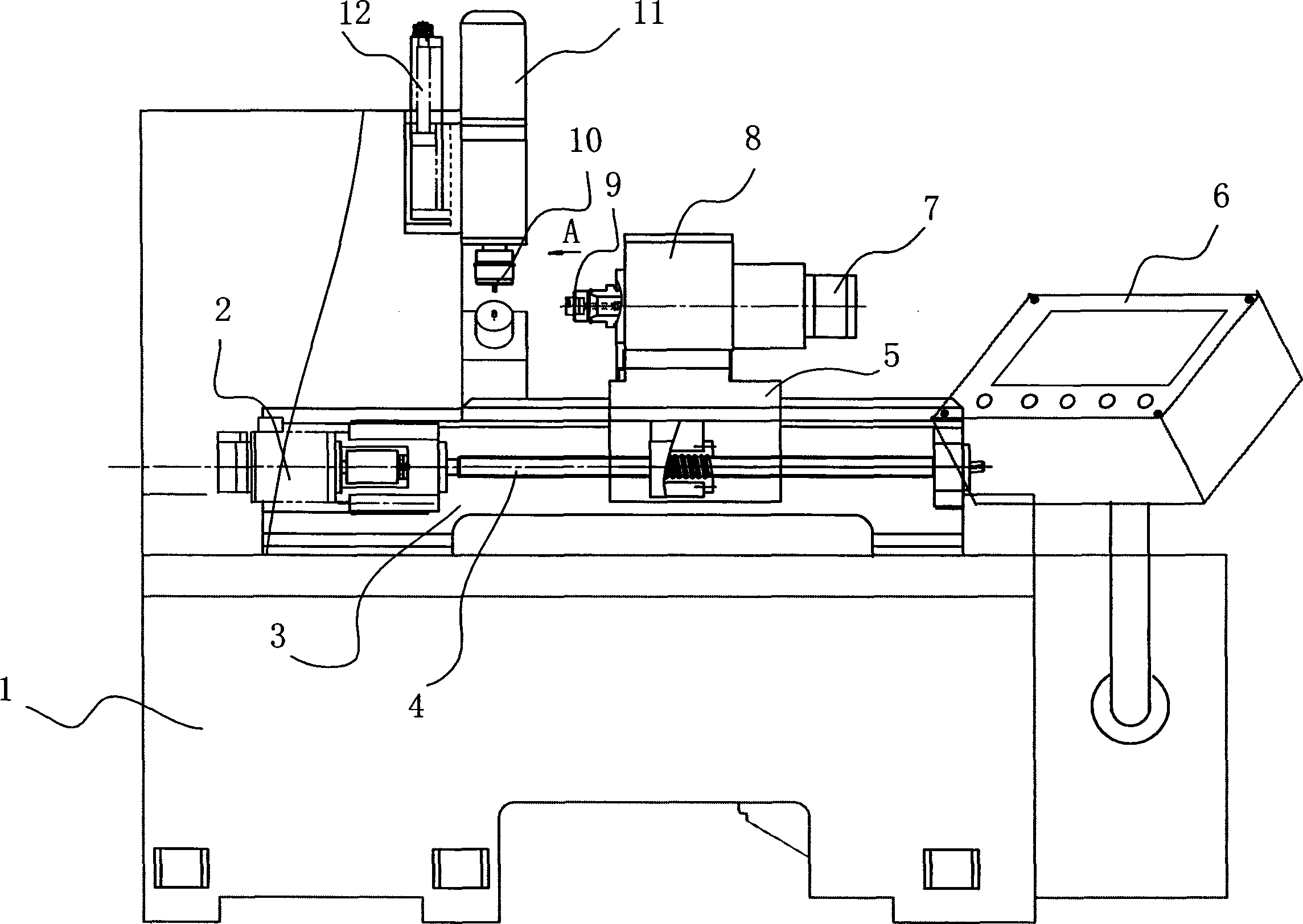
[0017] Figure 1-Figure 2 One embodiment of the multifunctional numerically controlled machine tool of the present invention is shown. It consists of a bed 3 with a bed leg 1 equipped with a carriage 5 that can slide along the guide rail. The carriage 5 is driven by a ball screw 4 installed on the bed. Or servo motor 2 drives. The lead screw pair is driven by the stepping or servo motor 2, and the lead screw 4 drives the carriage 5 through the bracket.

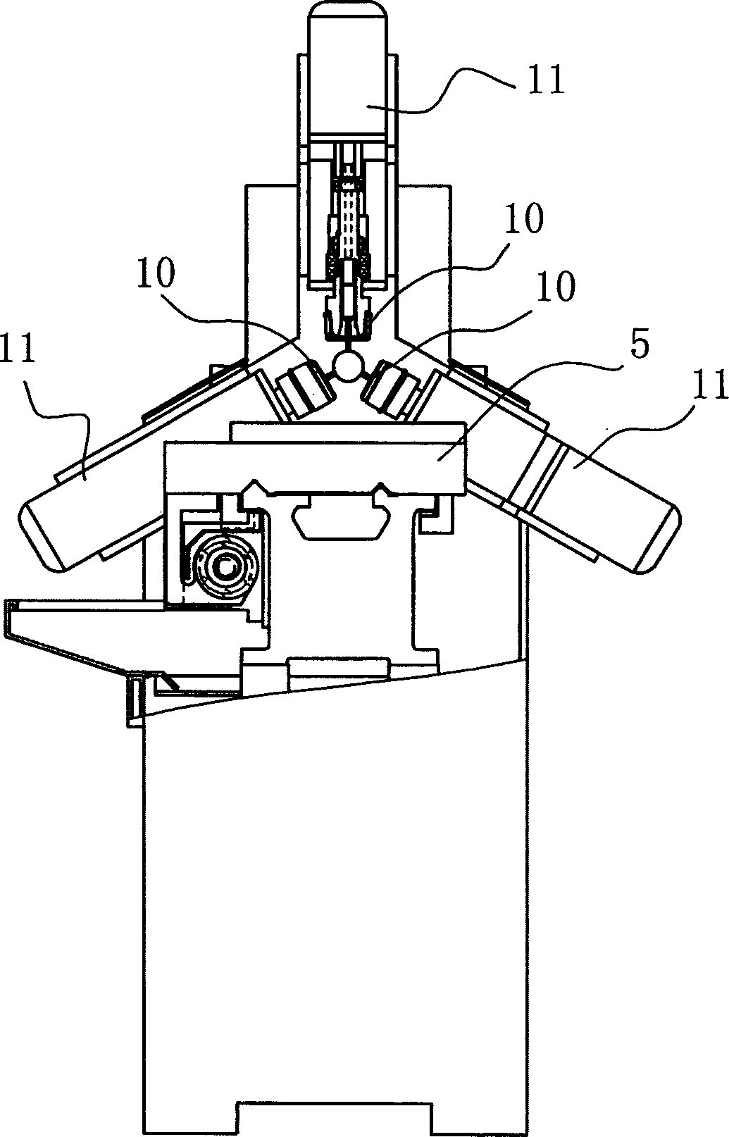
[0018] A reduction box 8 whose main shaft is consistent with the length direction of the guide rail is installed on the carriage 5, and a clamp part 9 for clamping the workpiece is installed on the main shaft of the reduction box (that is, the power output shaft). The clamp part 9 mainly adopts a collet, The collet is automatically clamped or loosened by the cylinder or oil cylinder 7. Specific...


PUM


Abstract

The invention relates to multifunctional digital control machine, comprising machine body, movable carriage controlled by digital control system, clamp element and knife carriage part for knife tool. It is characterized in that the carriage is equipped with a gearbox, clamp element is installed on main axis of gearbox; knife carriage part concludes knife carriage, which is located on knife carriage main axis drove by generator, generator is fixed on main spindle box, main spindle box is connected with a cylinder that can drive it for liner movement. The invention is characterized in that it employs digital control driving system integrated with multi-knife carriage, multi-generator and mechanical and hydraulic drive, the whole structure is compact, production cost is low and the tank and hole processing can be finished automatically, which greatly increases working efficiency and quality stability.

Description

technical field [0001] The invention relates to a metal cutting machine tool, in particular to a multifunctional numerical control machine tool with milling and drilling functions. Background technique [0002] At present, if the various processes of machining shaft parts such as arc groove processing, linear groove processing, hole processing, chamfering and boss processing, etc. are to be completed on the same metal cutting machine tool, only CNC milling machines or CNC milling machines can be used. Machining center equipment, while CNC milling machines or machining center equipment are expensive, and the efficiency of processing the above-mentioned shaft parts such as arc grooves, linear grooves, holes, chamfers and bosses with CNC milling machines or machining center equipment is not high, not only Can not be satisfied with batch production, and production cost is higher. Contents of the invention [0003] The technical problem to be solved by the present invention is...

Claims


Application Information

Patent Timeline
IPC IPC(8): B23Q37/00B23Q3/12B23Q5/34
Inventor 应圣平李元峰
Owner 应圣平
Features
  • R&D
  • Intellectual Property
  • Life Sciences
  • Materials
  • Tech Scout
  • Unparalleled Data Quality
  • Higher Quality Content
  • 60% Fewer Hallucinations
Learn More