Connecting structure of rotary connector and steering angle sensor

A rudder angle sensor, rotary connector technology, applied in flexible/rotatable wire connectors, connections, steering mechanisms, etc., can solve problems such as increased cost, spring ringing, poor assembly workability, etc., to eliminate vibration sound, reduce effect of noise

Inactive Publication Date: 2006-12-13
ALPS ALPINE CO LTD
View PDF1 Cites 9 Cited by
  • Summary
  • Abstract
  • Description
  • Claims
  • Application Information

AI Technical Summary

Problems solved by technology

However, since the two rotor parts need to be connected with the coil spring sandwiched between them, there is not only the problem of poor assembly workability when the rotary connector and the rudder angle sensor are assembled, but also the vibration of the coil spring itself when the vehicle is running. For problems such as spring squealing noises
[0008] And, in above-mentioned prior art, because the rotor part of rudder angle sensor is made of 2 split bodies that have flange at both ends up and down, two split bodies are sandwiched between code plate and combined into one as rotor part, by this rotor The parts are rotatably supported in the guide holes of the upper cover and the lower cover as fixed parts, so at least three parts (encoder plate and a pair of split bodies) are required to form an integrated product of the code plate and the rotor part, and there is a rudder angle sensor The problem of increasing the cost due to the increase in the number of parts

Method used


Image

  • Connecting structure of rotary connector and steering angle sensor
  • Connecting structure of rotary connector and steering angle sensor
  • Connecting structure of rotary connector and steering angle sensor

Examples


Embodiment Construction

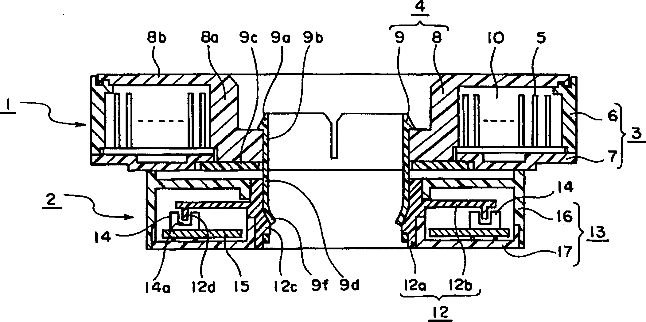
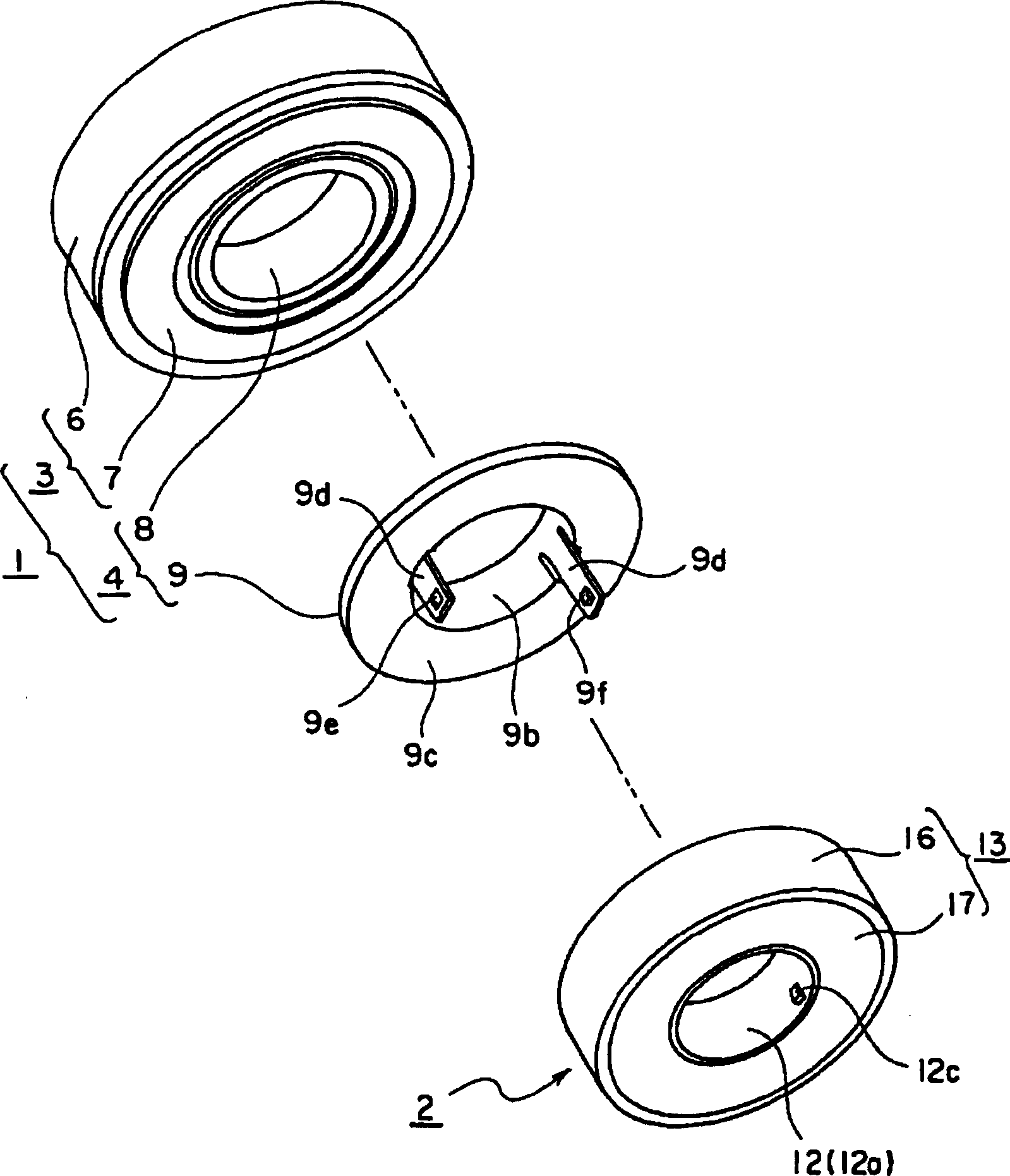
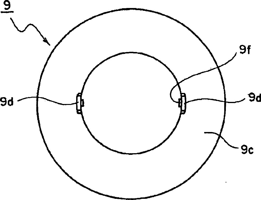
[0022] Embodiments of the invention will be described below with reference to the drawings. figure 1 It is a cross-sectional view showing a connection assembly of a rotary connector and a rudder angle sensor according to an embodiment of the present invention, figure 2 is an exploded perspective view of the connection assembly, image 3 In order to show the bottom view of the lower rotor of the swivel connector included in this connection assembly, Figure 4 is a sectional view of the lower rotor, Figure 5 It is an explanatory diagram showing the main part of the connecting portion of the lower rotor and the rotating member of the steering angle sensor.

[0023] The connecting assembly of the present embodiment is composed of a rotary connector 1 and a rudder angle sensor 2. As will be described later, these rotary connectors 1 and the rudder angle sensor 2 are assembled in a state in which they are stacked up and down in two stages. into the steering gear of the vehicle....


PUM


Abstract

The invention provides a connecting structure of rotary connector and steering angle sensor which can reduce noise. In the connecting structure of a first rotor member (rotor housing) of a rotary connector and a second rotor member (rotary member) of a steering angle sensor, a plurality of elastic pieces is formed on the inner peripheral portion of the first rotor member so as to extend downward, an engaging protrusion is provided in the inner peripheral portion of the second rotor member so as to be inserted in an engaging hole of the elastic piece, and the elastic piece is combined with the engaging protrusion in a snap-in relationship. When a stator member of the rotary connector and a fixing member of the steering angle sensor are fixedly connected to each other during assembling, a gap between both rotor member and narrows, and thus each elastic piece bends. Therefore, a tongue portion of the elastic piece is brought into an elastic contact with the elastic protrusion, and thus both rotor members are elastically urged in an axis line direction and a radial direction.

Description

technical field [0001] The present invention relates to a connection structure between a rotary connector used as an electrical connection device such as an airbag system and a steering angle sensor as a steering wheel rotation information detection device assembled in a steering device of an automobile. Background technique [0002] The rotary connector is a device that freely rotatably connects the rotor part to the stator part, and packs and winds the flexible cable into the annular space divided between these stator parts and the rotor part. By connecting the rotor part with the steering wheel Interlocking rotation makes the flexible cable tightly wound or uncoiled in the annular space. Here, a relatively large gap (a gap in a plane perpendicular to the rotation axis) is ensured between the rotor member and the stator member of the rotary connector so that the rotor member can stably rotate in conjunction with the steering wheel. On the other hand, the rudder angle sens...

Claims


Application Information

Patent Timeline
Patent Type & Authority Applications(China)
IPC IPC(8): H01R35/04B62D1/04
CPCH01R35/025B60R16/027B62D15/022H01R35/04
Inventor 荒木俊二佐野正
Owner ALPS ALPINE CO LTD
Why Eureka
Try Eureka