Pressure compensating flow control hydraulic circuit having holding valve

A technology of flow control and pressure compensation, applied in fluid pressure actuators, servo meter circuits, gas/liquid distribution and storage, etc., can solve problems such as difficulty in coordinating the driving speed of the arm, reducing usability and maneuverability, etc.

Inactive Publication Date: 2006-12-20
SAMSUNG HEAVY IND CO LTD
View PDF0 Cites 2 Cited by
  • Summary
  • Abstract
  • Description
  • Claims
  • Application Information

AI Technical Summary

Problems solved by technology

Therefore, in the case of performing a mixed operation in which the arm is steered together with a working unit such as a boom or a swing motor, it is difficult to coordinate the driving speed of the arm and the driving speed of the working unit such as a boom or a swing motor, thereby reducing Usability and maneuverability

Method used


Image

  • Pressure compensating flow control hydraulic circuit having holding valve
  • Pressure compensating flow control hydraulic circuit having holding valve
  • Pressure compensating flow control hydraulic circuit having holding valve

Examples


Embodiment Construction

[0032] Hereinafter, preferred embodiments of the present invention will be described with reference to the accompanying drawings. Matters defined in the description, such as specific configurations and elements, are merely specific details provided to help those of ordinary skill in the art fully understand the present invention, and thus the present invention is not limited thereto.

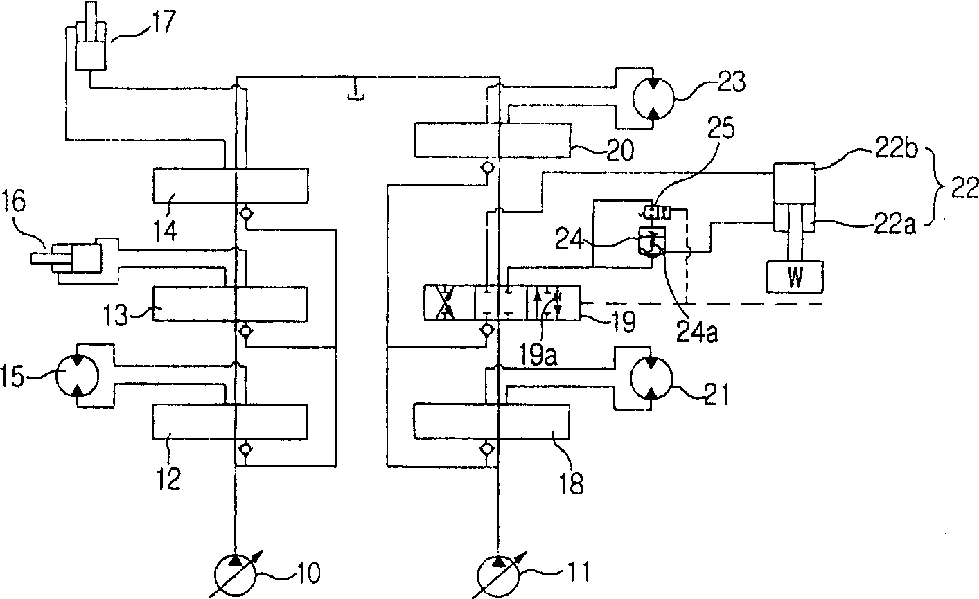
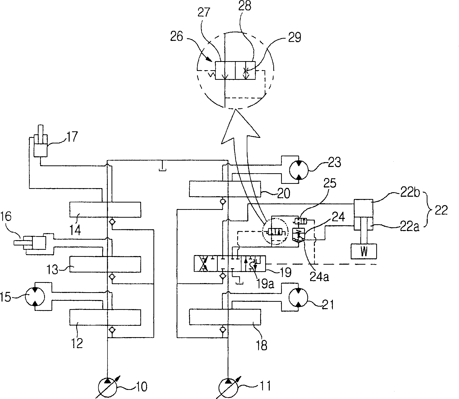
[0033] refer to image 3 , preferred embodiments of the present invention will now be explained.

[0034] like image 3 As shown, the pressure compensating hydraulic circuit with lock valve according to the present invention includes: first and second variable displacement hydraulic pumps 10 and 11; mobile motor 15, bucket cylinder 16 and boom cylinder 17, which are respectively connected to the first variable displacement hydraulic pump 10 and hydraulic fluid is supplied to the control valves 12, 13 and 14 from the first hydraulic pump 10 when they are switched in response to a control signal...


PUM


Abstract

A pressure compensating flow control hydraulic circuit having a holding valve is disclosed. The pressure compensating flow control hydraulic circuit can perform the function of a holding valve so as to prevent the naturally lowering phenomenon of a working unit due to the leakage of a hydraulic fluid when the working unit is located in a neutral position, and can perform the function of a flow control valve when the working unit is operated. The pressure compensating flow control hydraulic circuit includes first and second hydraulic pumps; a boom cylinder for being supplied with a hydraulic fluid from the first hydraulic pump when a control valve of the boom cylinder is switched over; an arm cylinder for being supplied with the hydraulic fluid from the second hydraulic pump when a control valve is of the arm cylinder is switched over; a holding valve for preventing an arm from being naturally lowered due to a load pressure; an auxiliary spool for being switched over in response to a pilot signal applied from an outside to release a load of the arm cylinder; and a flow control valve for controlling a flow rate of the hydraulic fluid to drain from the small chamber of the arm cylinder to the hydraulic tank constantly when the auxiliary spool is switched over.

Description

[0001] Cross References to Related Applications [0002] This application claims priority under Section 119 of the US Patent Act to Korean Patent Application No. 2005-52313 filed on June 17, 2005, the entire contents of which are hereby incorporated by reference. technical field [0003] The present invention relates to a pressure compensated flow control hydraulic circuit with a lock valve that can uniformly maintain the operating speed of a working unit at the same control signal pressure regardless of the load pressure of the working unit such as a boom, arm or the like. [0004] More specifically, the present invention relates to a pressure compensated flow control hydraulic circuit having a lock valve capable of performing the inherent function of the lock valve, i.e. preventing natural flow of the work unit due to leakage of hydraulic fluid from the work unit when the work unit is in the neutral position. ground drop phenomenon, and performs the function of a flow contro...

Claims


Application Information

Patent Timeline
Patent Type & Authority Applications(China)
IPC IPC(8): F17D1/08
CPCF15B2211/30525F15B2211/7053F15B2211/75F15B2211/7058F15B11/042F15B2211/329F15B2211/71F15B2211/3116F15B2211/20546F15B2211/3056F15B11/08F15B2211/46F15B2211/40515F15B11/00
Inventor 郑海均
Owner SAMSUNG HEAVY IND CO LTD
Why Eureka
Try Eureka