Dehumidifier

A dehumidifier and moisture technology, applied in mechanical equipment, heating methods, lighting and heating equipment, etc., can solve the problems of large noise and vibration, damage to appearance, high production cost, reduce weight, improve convenience, The effect of improving dehumidification efficiency

Inactive Publication Date: 2010-06-09
LG ELECTRONICS INC
View PDF4 Cites 5 Cited by
  • Summary
  • Abstract
  • Description
  • Claims
  • Application Information

AI Technical Summary

Problems solved by technology

[0008] The outlet 5a in the front panel 5 spoils the appearance, and it is difficult to change the discharge direction of the air
[0009] Since the water tank 6 is installed / removed through the rear of the housing 1, the installation / removal of the water tank 6 is inconvenient
[0010] The dehumidification effect is not good because the room air passing through the heat exchanger 3 is discharged directly into the room again even if the humidity is not completely removed from the air
[0011] Also, a compressor is used in the related art dehumidifier to circulate the refrigerant, resulting in high production cost and causing a lot of noise and vibration during operation

Method used


Image

  • Dehumidifier
  • Dehumidifier
  • Dehumidifier

Examples


Embodiment Construction

[0034] Preferred embodiments of the present invention will be described in detail below, with Figure 2-6 An example of the invention is shown. Wherever possible, the same reference numbers are used throughout the figures for identical or similar parts.

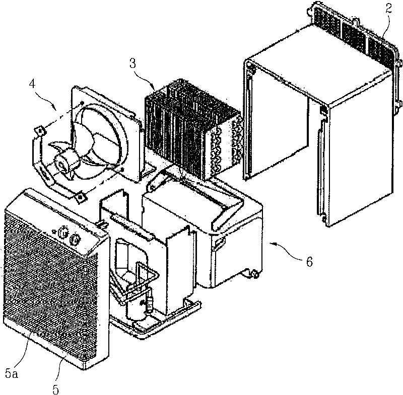
[0035] refer to Figure 2-5 , the dehumidifier includes: a casing 10 forming its appearance; a heat exchanger 20 made of heat-conducting material in the casing 10; a drying assembly 30 in the casing 10 for absorbing moisture from the air; a fan assembly 40 for forcing indoor air into the housing 10 ; and a regenerator assembly 50 for forcing a portion of the indoor air drawn into the housing 10 to circulate through the heat exchanger 20 .

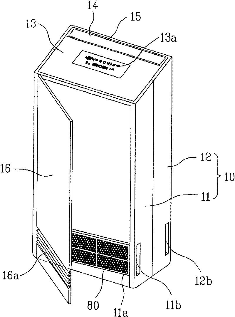
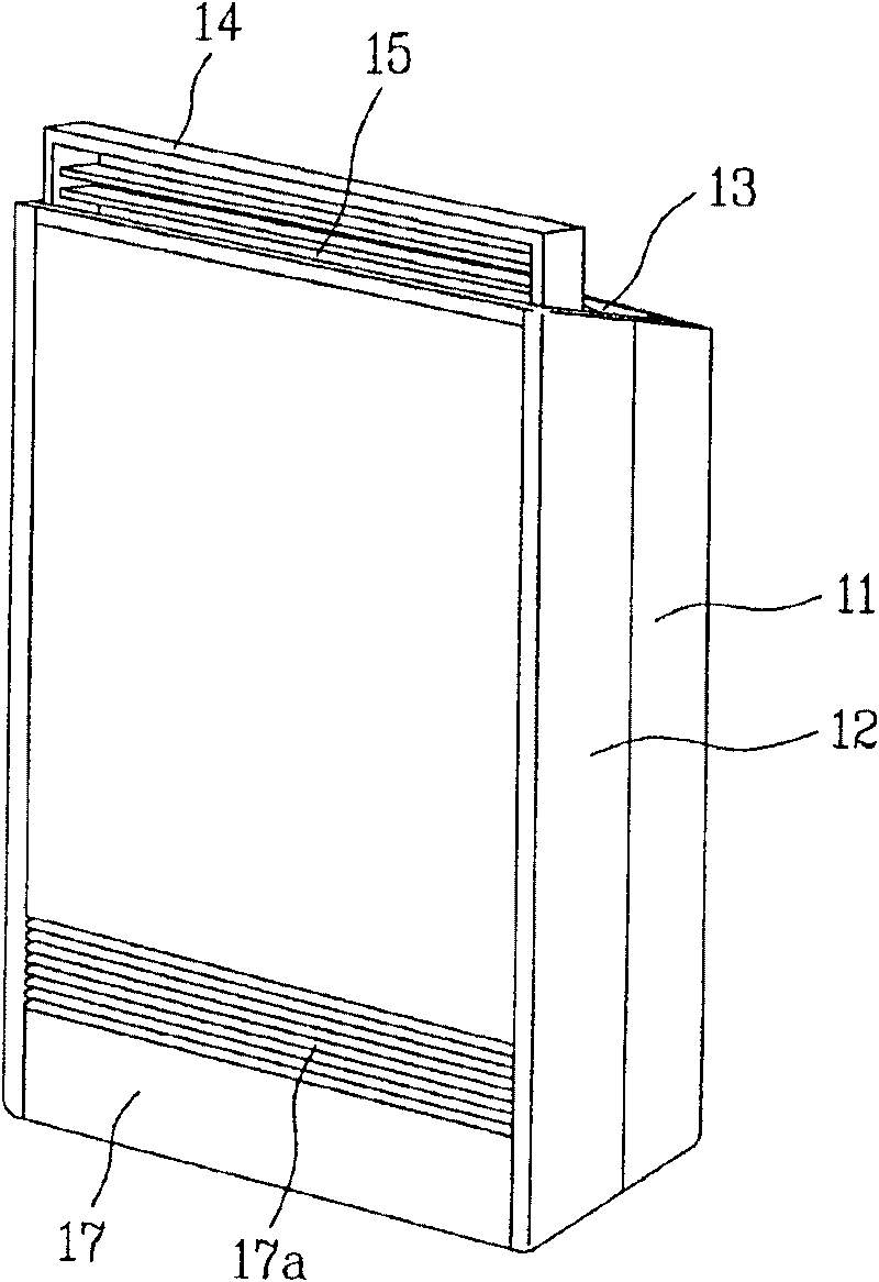
[0036] The casing 10 has a substantially hexahedral shape, and has a front half and a rear half. That is, the housing 10 includes: a front frame 11 that forms the front, side and top appearance of the front half of the housing 10; and a rear frame 12 that forms the rear, Side and top l...


PUM


Abstract

The present invention relates to a dehumidifier for improving dehumidifying efficiency and discharging dehumidified water to an outside of the dehumidifier easily. The dehumidifier includes a case, aninlet passed through the case for introduction of air from an outside of the case to an inside of the case, an outlet formed to pass through a top of the case for discharging air dehumidified in thecase to the outside of the case, a desiccant assembly for absorbing moisture from air drawn into the case, a blower assembly for drawing air through the inlets and blowing the air to the outlet, a regenerator assembly for blowing hot air to the desiccant assembly for drying the desiccant assembly, a heat exchanger for condensing high temperature, humid air blown by the regenerator assembly throughthe desiccant assembly, to separate the moisture from the air, a top cover movably mounted on a top side of the case for opening / closing the top side of the case, and a water tank mounted beneath thetop cover of the case at a top side thereof separable therefrom, for receiving, and holding water condensed at the heat exchanger.

Description

technical field [0001] The present invention relates to a dehumidifier, and more particularly, to a dehumidifier in which moisture is absorbed not by a refrigerant but by a desiccant so as to separately collect the moisture and thereby improve the dehumidification effect. Background technique [0002] In general, a dehumidifier reduces the humidity in a room by absorbing humid air in the room, passing the humid air through a heat exchanger with a condenser and an evaporator to remove moisture from the air, The dehumidified air is exhausted where the refrigerant flows through the condenser and evaporator. [0003] That is, the dehumidifier removes heat from the air surrounding the dehumidifier by evaporating the liquid refrigerant at the evaporator. In more detail, when the refrigerant evaporates, the temperature of the evaporator decreases, and when the air passes through the evaporator, the temperature of the air also decreases. [0004] When the temperature around the ev...

Claims


Application Information

Patent Timeline
Patent Type & Authority Patents(China)
IPC IPC(8): F24F1/02F24F3/14F24F3/16
CPCF24F3/14F24F3/1429F24F13/222F24F13/28F24F8/10
Inventor 安炳龙金奭勋
Owner LG ELECTRONICS INC
Why Eureka
Try Eureka