Electric connector of flat type vibration source (1)
A technology of electrical connectors and vibration sources, applied in the direction of connection, two-component connection devices, circuits, etc., can solve the problems of disappearing height advantages and inconsistent installation accuracy, so as to save manpower and material resources, reduce manufacturing costs, and improve Effects of Consistency and Reliability
- Summary
- Abstract
- Description
- Claims
- Application Information
AI Technical Summary
Problems solved by technology
Method used
Image
Examples
Embodiment 1
[0031] The specific device and implementation details proposed by the present invention will now be described in detail according to the above-mentioned drawings.
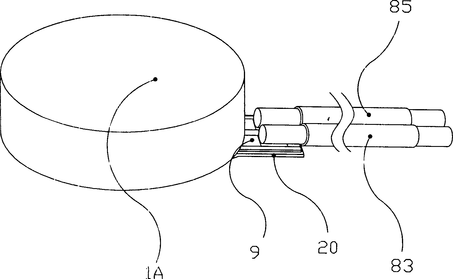
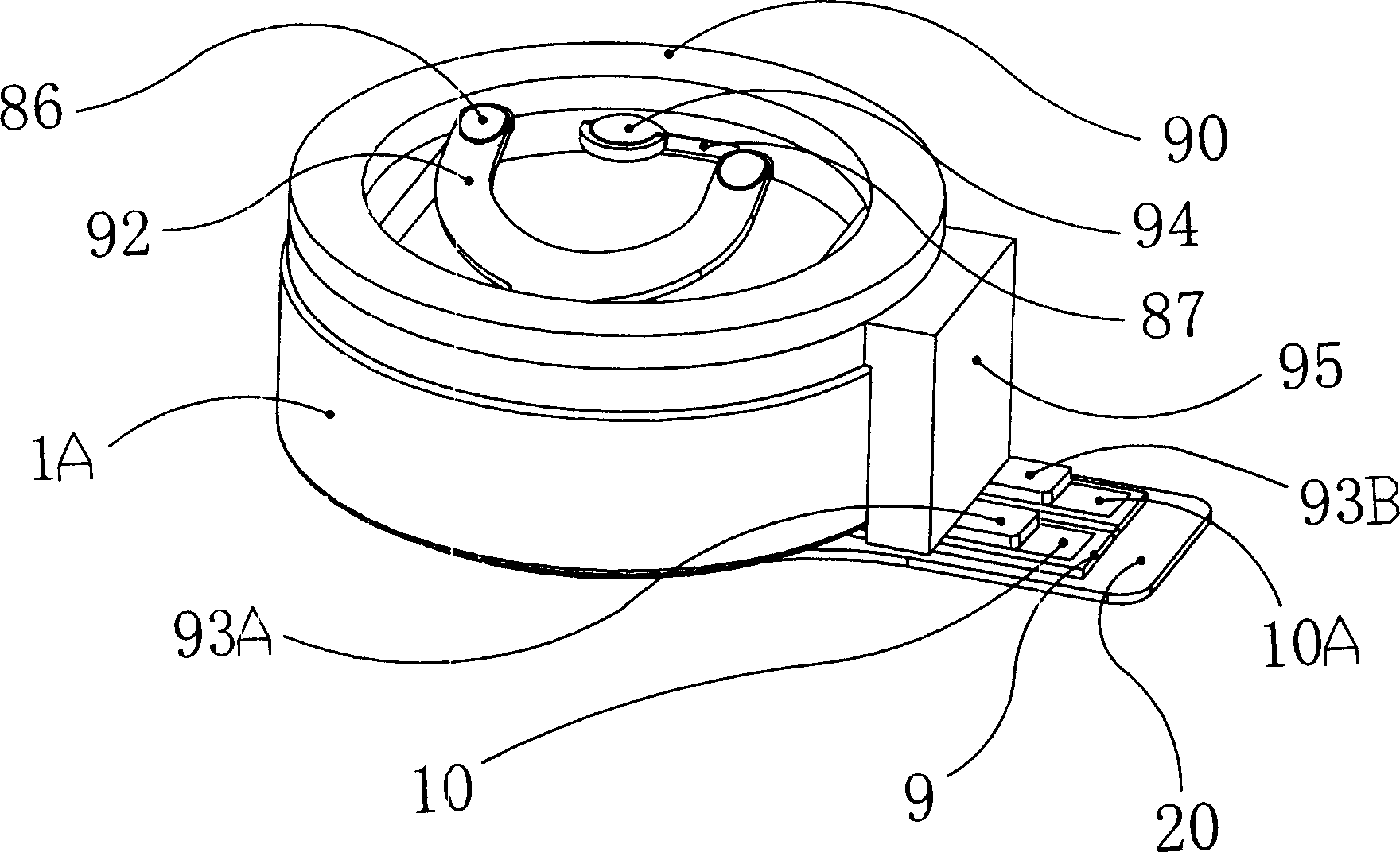
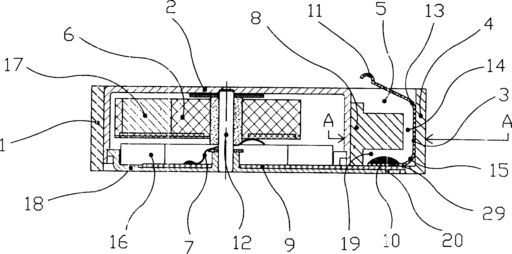
[0032] The electrical connector of the present invention comprises: a flat type vibration source (1A), and the flat type vibration source (1A) is an entity whose height is smaller than the diameter. Such as image 3 As shown, it also includes: a ring-shaped base (1); a base (4) connected to the ring-shaped base (1); and positive metal shrapnel (3) and negative metal shrapnel (3A).
[0033] Since the annular base (1) and the base (4) are structurally an integral body, the base (4) can be formed by injection molding; and the positive metal shrapnel (3) and the negative metal shrapnel (3A) .
[0034] Since the ring-shaped base (1) and the base (4) are integral in structure, they can be integrally formed by injection molding.
[0035] Figure 4 It is a top view of the flat type vibration source of the present inven...
Embodiment 2
[0047] The rest of this embodiment is basically the same as Embodiment 1, except that one of the circuits of the flat vibration source (1A) is the casing itself, and the other is a metal shrapnel or wire. Because the upper casing (2) or the lower casing (18) of the flat type vibration source (1A) can be metal conductors, a metal conductor can be pre-designed at the position where the flat type vibration source (1A) is installed on the mobile phone (in the figure not shown), when the flat type vibration source (1A) was installed on the designated position, the metal conductor was in contact with the upper casing (2) or the lower casing (18) of the flat type vibration source (1A), and then between the two establish electrical contact between them. The advantage of this connection method is: because the contact area of the shell of the flat type vibration source (1A) is relatively large, it can reduce the production requirements for metal conductors; The manufacturing requirem...
Embodiment 3
[0049] The rest of this embodiment is basically the same as Embodiment 1 and Embodiment 2, except that the upper casing (2) and the base (4) are integrally formed by injection molding, and the corresponding annular base is omitted (1). This structure has more obvious advantages than Embodiment 1 and Embodiment 2: Owing to omitting the annular base (1), the profile of the flat type vibration source (1A) electrical connector is smaller and has more space , thus having more competitive advantages. The above casing (2) and the base (4) can be integrated not only by injection molding, but also by other methods such as: welding, riveting, riveting, stretching and the like. Such as Figure 7 shown.
PUM
 Abstract
Description
Claims
Application Information
 - R&D
- Intellectual Property
- Life Sciences
- Materials
- Tech Scout
- Unparalleled Data Quality
- Higher Quality Content
- 60% Fewer Hallucinations
Browse by: Latest US Patents, China's latest patents, Technical Efficacy Thesaurus, Application Domain, Technology Topic, Popular Technical Reports.
© 2025 PatSnap. All rights reserved.Legal|Privacy policy|Modern Slavery Act Transparency Statement|Sitemap|About US| Contact US: help@patsnap.com


