Flat oscillation source and electric connector

A technology of electrical connectors and vibration sources, which is applied in the direction of contact parts, electrical components, electromechanical devices, etc., can solve the problems of inconsistent installation accuracy and disappearance of height advantages, etc., to reduce manufacturing costs, save manpower and material resources, and improve Effects of Consistency and Reliability

Inactive Publication Date: 2007-01-17
干方飞
View PDF0 Cites 0 Cited by
  • Summary
  • Abstract
  • Description
  • Claims
  • Application Information

AI Technical Summary

Problems solved by technology

But there are still some problems; the fixing of the ring-shaped insulating base (90) and the upper casing of the flat vibration source (1A) is not stable if fixed by double-sided adhesive tape, and is greatly affected by temperature and man-made, and the installation is accurate sexually inconsistent
And the annular insulating substrate (90) that is installed on the upper casing of the flat type vibration source (1A) has undoubtedly improved the height of the whole parts, and this change is very unfavorable for the flat type vibration source (1A), making the flat type vibration source (1A) The original height advantage of the type vibration source (1A) disappears

Method used


Image

  • Flat oscillation source and electric connector
  • Flat oscillation source and electric connector
  • Flat oscillation source and electric connector

Examples


Embodiment 1

[0032] The specific device and implementation details proposed by the present invention will now be described in detail according to the above-mentioned drawings.

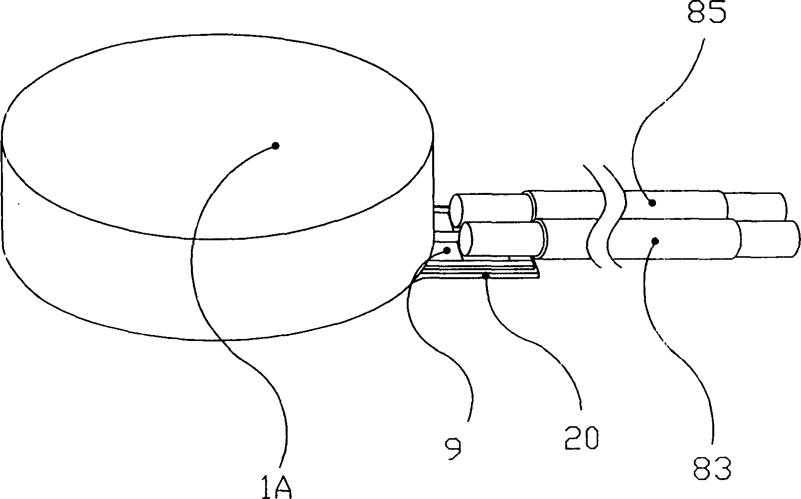
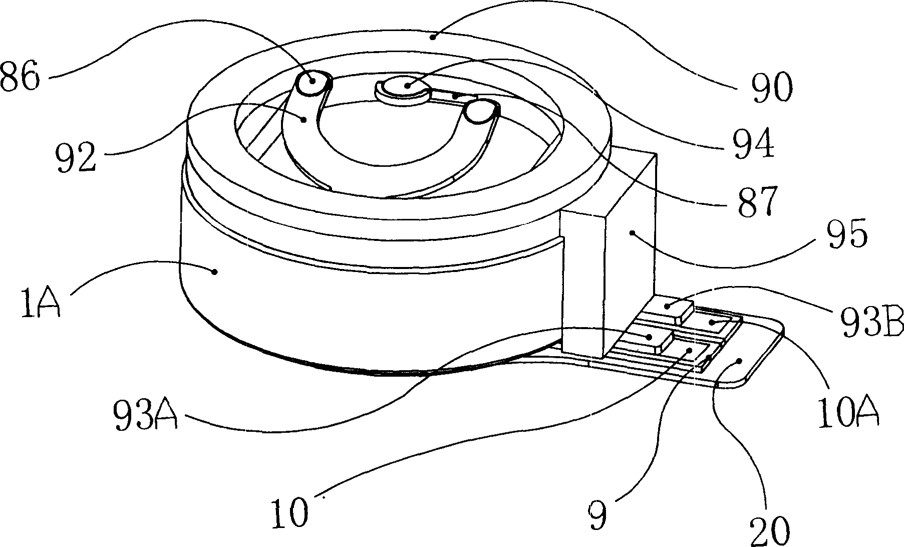
[0033] The electrical connector of the flat vibration source (1A) of the present invention comprises: a base (4), positive metal shrapnel (3), and negative metal shrapnel (3A);

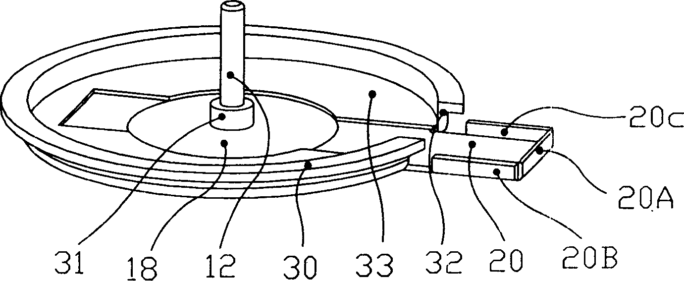
[0034] The base (4) is block-shaped, including: a lower space (19), an upper space (5), a rectangular hole (14), and at least one positioning groove (25A), (25), (25B); The height of the base (4) is slightly higher than or less than the height of the flat vibration source (1A), and its width is greater than or equal to the width of the tail (20) of the lower casing (18) of the flat vibration source (1A). Parallel to the bottom of the flat vibration source (1A), or slightly higher or lower than the bottom of the flat vibration source (1A); the base (4) is located at the bottom of the flat vibration source (1A) ( 18) One end of the tail (20...

Embodiment 2

[0049] The rest of this embodiment is basically the same as Embodiment 1, except that one of the circuits of the flat type vibration source (1A) is the casing itself, and the corresponding positive metal shrapnel (3) and negative metal shrapnel (3) are omitted. The shrapnel (3A), the other pole can be connected with the shell of the flat vibration source (1A) through metal shrapnel or wires. Because the upper casing (2) or the lower casing (18) of the flat type vibration source (1A) can be metal conductors, a metal conductor can be pre-designed at the position where the flat type vibration source (1A) is installed on the mobile phone (in the figure not shown), when the flat type vibration source (1A) was installed on the designated position, the metal conductor was in contact with the upper casing (2) or the lower casing (18) of the flat type vibration source (1A), and then between the two establish electrical contact between them. The advantage of this connection method is: ...

Embodiment 3

[0051] The rest of this embodiment is basically the same as Embodiment 1 and Embodiment 2, except that the upper casing (2) and the base (4) are formed as a whole through injection molding. This structure has more obvious advantages than Embodiment 1 and Embodiment 2: because the base (4) and the upper casing (2) are integrated, it has advantages that the previous embodiment does not have in the manufacturing process. The production cost is also reduced, so it is more competitive. The above casing (2) and the base (4) can be integrated not only by injection molding, but also by other methods such as: welding, riveting, riveting, stretching and the like. Such as Figure 8 shown.


PUM


Abstract

A flat vibration source and the electric connector, including: the top shell, the stator groupware, the bottom shell, the extending tail and the rotor groupware; the rotor groupware is in the inner space that forms by the top shell and the bottom shell; the electric connector includes the base, the anode metal spring slice and the cathode metal spring slice; the base is the block shape that including the bottom space, the top space, the rectangle hole and the locating slot; one end of the anode metal spring slice and the cathode metal spring slice connects with the anode and the cathode of the flat vibration source respectively, and located in the bottom space of the base, the other end sets out of the base; the locating slot of the base and the two sides and top of the bottom shell tail bends, superposes and fixes with the extending rib. The invention can exert the spacing advantages and reduces the produce cost.

Description

technical field [0001] The invention relates to an electrical connector of a flat vibration source, and particularly relates to a vibration source which can be quickly and conveniently installed at a designated position without sacrificing the external dimensions. Background technique [0002] With the rapid development of science and technology, mobile phones, pagers, etc. in portable personal communication systems are also developing towards smaller volumes and more powerful functions; and the flat vibration source used to provide vibration functions to the above-mentioned appliances There is also a fierce competition going on at the micron scale. As we all know, a very important function in the personal communication system is to remind the user that there is an incoming message. At present, the most widely used function is to use music, ringing function, and another is to remind the user that there is a message by making the machine itself tremble. call in. This featur...

Claims


Application Information

Patent Timeline
IPC IPC(8): H02K7/065H02K5/22H01R13/11H01R13/24
Inventor 连仕云
Owner 干方飞
Why Eureka
Try Eureka