Induction motor

A technology of induction motors and coils, which can be applied to the shape/style/structure of magnetic circuit, electromechanical devices, and rotating parts of magnetic circuit, etc., and can solve the problems such as the increase of the end turning part 121

Inactive Publication Date: 2010-12-15
LG ELECTRONICS INC
View PDF0 Cites 0 Cited by
  • Summary
  • Abstract
  • Description
  • Claims
  • Application Information

AI Technical Summary

Problems solved by technology

Therefore, the length of the end turning portion 121 must be increased

Method used


Image

  • Induction motor
  • Induction motor
  • Induction motor

Examples


Embodiment Construction

[0036] Reference will now be made in detail to the preferred embodiments of the invention, examples of which are illustrated in the accompanying drawings.

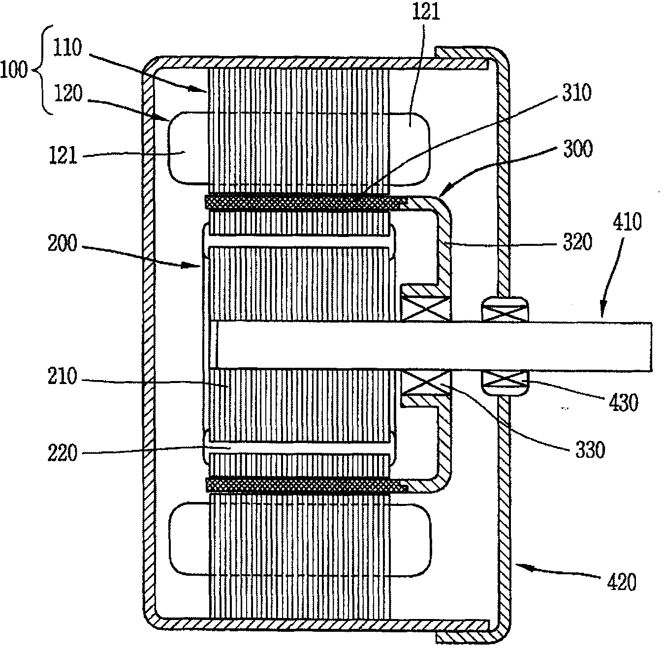
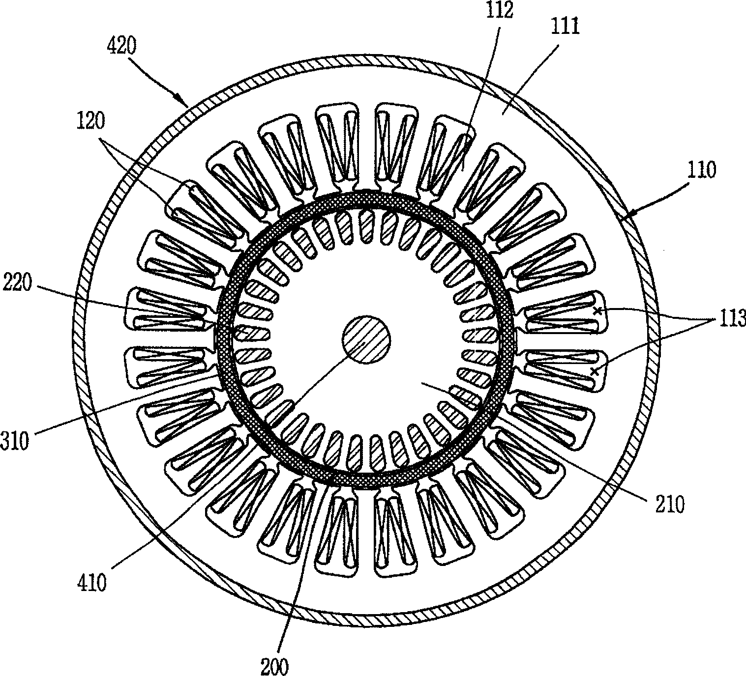
[0037] Figure 4 shows a front sectional view of an embodiment of an induction motor according to the invention, Figure 5 It is a side sectional view of the induction motor.

[0038] As shown in the figure, first, the induction motor is provided with a stator including a stator core 510, a main winding coil 520 wound on the stator core 510, and an auxiliary winding coil 530 wound on the stator core (the auxiliary winding coil 530 smaller than the volume of the main winding coil 520 ), the main rotor 600 rotatably inserted into the stator 500 , and the sub-rotor 700 including the magnet 710 and rotatably inserted into the air gap between the stator 500 and the main rotor 600 .

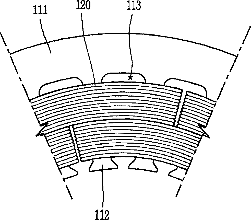
[0039] The stator core 510 includes: a yoke 511 formed in a ring shape having a certain width; and a plurality of teeth 512 formed on an inner c...


PUM


Abstract

An induction motor comprising a stator including main winding coils and sub winding coils wound in a stator core, respectively, the main winding coil having a volume greater than that of the sub winding coil, a primary rotor rotatably inserted in the stator, and a secondary rotor rotatably inserted in an air gap between the stator and the primary rotor, whereby counter electromotive force of the main winding coils is increased and resistance thereof is decreased, and thus an operation efficiency can be improved and starting voltage and break down voltage can be reduced.

Description

technical field [0001] The present invention relates to an induction motor, and more particularly, to an induction motor capable of reducing an ineffective portion of a winding coil by efficiently winding the winding coil, minimizing resistance loss of the winding coil, and increasing counter electromotive force. Background technique [0002] In general, a motor that converts electricity into power is used in various fields such as home appliances to be used as a power source of products. For example, in a refrigerator, a motor turns a fan to circulate cold air inside the refrigerator. When used in air conditioning, the motor turns the fan to move the cool air from the evaporator into the interior space. [0003] The refrigerator or air conditioner is continuously turned on and off to maintain the internal temperature of the refrigerator or room temperature at a preset temperature. Therefore, a motor installed in a refrigerator or an air conditioner needs to be highly effi...

Claims


Application Information

Patent Timeline
Patent Type & Authority Patents(China)
IPC IPC(8): H02K16/02H02K1/16H02K3/12H02K1/22H02K1/27
CPCH02K1/165H02K16/02H02K3/46H02K1/12
Inventor 韩承道申铉定安宰弘吴承锡
Owner LG ELECTRONICS INC
Why Eureka
Try Eureka