Radial flux permanent magnet AC motor/generator

a permanent magnet ac motor and radial flux technology, applied in the direction of windings, magnetic circuit rotating parts, magnetic circuit shapes/forms/construction, etc., can solve the problems of low peak power density of motors, heavy and unresponsive, and difficult control of speed, so as to achieve high power density, light weight, and efficient

Inactive Publication Date: 2012-11-13
PATENT LICENSORS
View PDF22 Cites 38 Cited by
  • Summary
  • Abstract
  • Description
  • Claims
  • Application Information

AI Technical Summary

Benefits of technology

[0003]Three-phase asynchronous AC induction motors are typically powered by a DC battery pack coupled to a DC / AC inverter and associated pulse width modulation circuitry to achieve variable speed control. These motors are characterized by heavy weight, low torque, and power factor losses. Power electronics are employed to receive a DC voltage supplied by a battery pack and produce an AC voltage whose waveform frequency is modulated so that the motor's speed may be varied. These motors offer good speed control, are brushless, can be sealed, can run in reverse, and provide power regeneration. However, AC induction motors exhibit low starting torque, which means they usually require a gear box, have power factor losses, are typically more expensive than series DC motors, and the controller required to vary the motor's speed is large, complex and expensive as it must handle the slippage between the input current and the rotational speed necessary for such an asynchronous motor to operate.
[0018]In summary, the AC motor / generator of the present invention 1) utilizes electromagnet cores fabricated of a high-performance powder metal material to increase their performance over prior art laminated steel cores; 2) utilizes electromagnets wound with heavy gauge copper wire to minimize resistive losses; 3) eliminates any air core from the electromagnets thereof to thereby increase the magnetic force produced by the electromagnets; 4) utilizes electromagnets having a flat surface that is interfaced to the stator surface to provide improved heat conduction from the electromagnets to the stator; 5) utilizes separately formed cores and shoes in order to facilitate machine winding of the electromagnets; 6) utilizes electromagnetic cores that are separate from the flux ring and shoes to further enable machine winding of the electromagnets; 7) utilizes a structural epoxy material in combination with non-metallic anchor plates to anchor the electromagnets to the stator; and 8) utilizes wedges to hold the permanent magnets to the rotor surface to provide resistance to rotational forces, thereby eliminating the prior art use of screws that penetrate the permanent magnets, displacing some of the magnetic material thereof and reducing their magnetic field strength.BRIEF DESCRIPTION OF THE DRAWINGS

Problems solved by technology

These motors suffer from low peak power densities.
Thus, they are heavy and unresponsive; they are not sealed since air flow through the motor is required to cool the rotor; and they cannot run in reverse.
Furthermore, their speed is difficult to control under varying load conditions, and they have no power regeneration capability.
These motors are characterized by heavy weight, low torque, and power factor losses.
However, AC induction motors exhibit low starting torque, which means they usually require a gear box, have power factor losses, are typically more expensive than series DC motors, and the controller required to vary the motor's speed is large, complex and expensive as it must handle the slippage between the input current and the rotational speed necessary for such an asynchronous motor to operate.
Because the physical size of electromagnets 1401 is limited in any given motor design, the size of copper wire 1400 is also limited, thus increasing the resistive losses in the windings.
In addition, it is difficult to mechanize the winding of teeth 1200 in the presence of shoes 1300, so winding is typically accomplished manually, at much higher cost.

Method used


Image

  • Radial flux permanent magnet AC motor/generator
  • Radial flux permanent magnet AC motor/generator
  • Radial flux permanent magnet AC motor/generator

Examples


Embodiment Construction

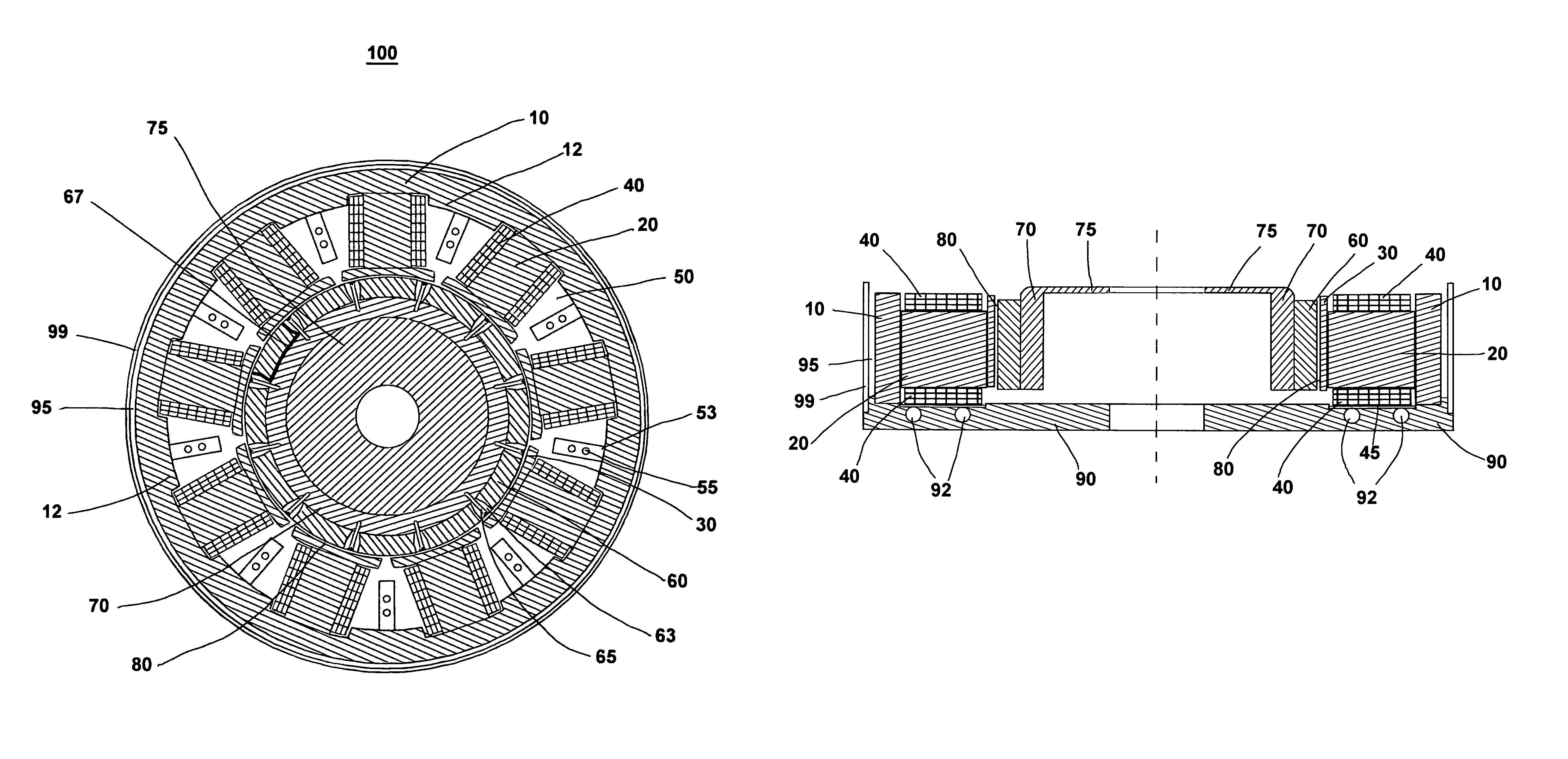
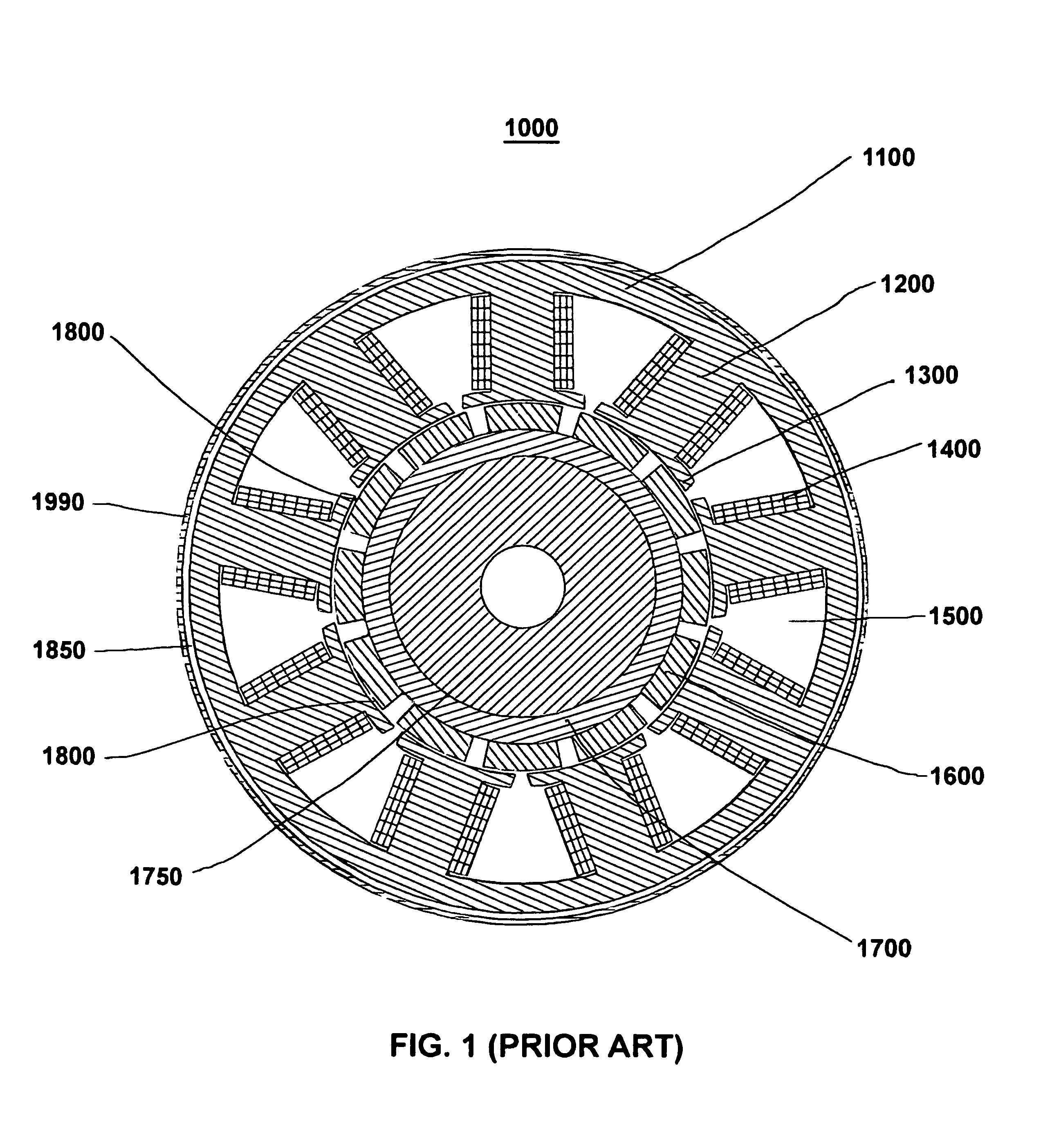
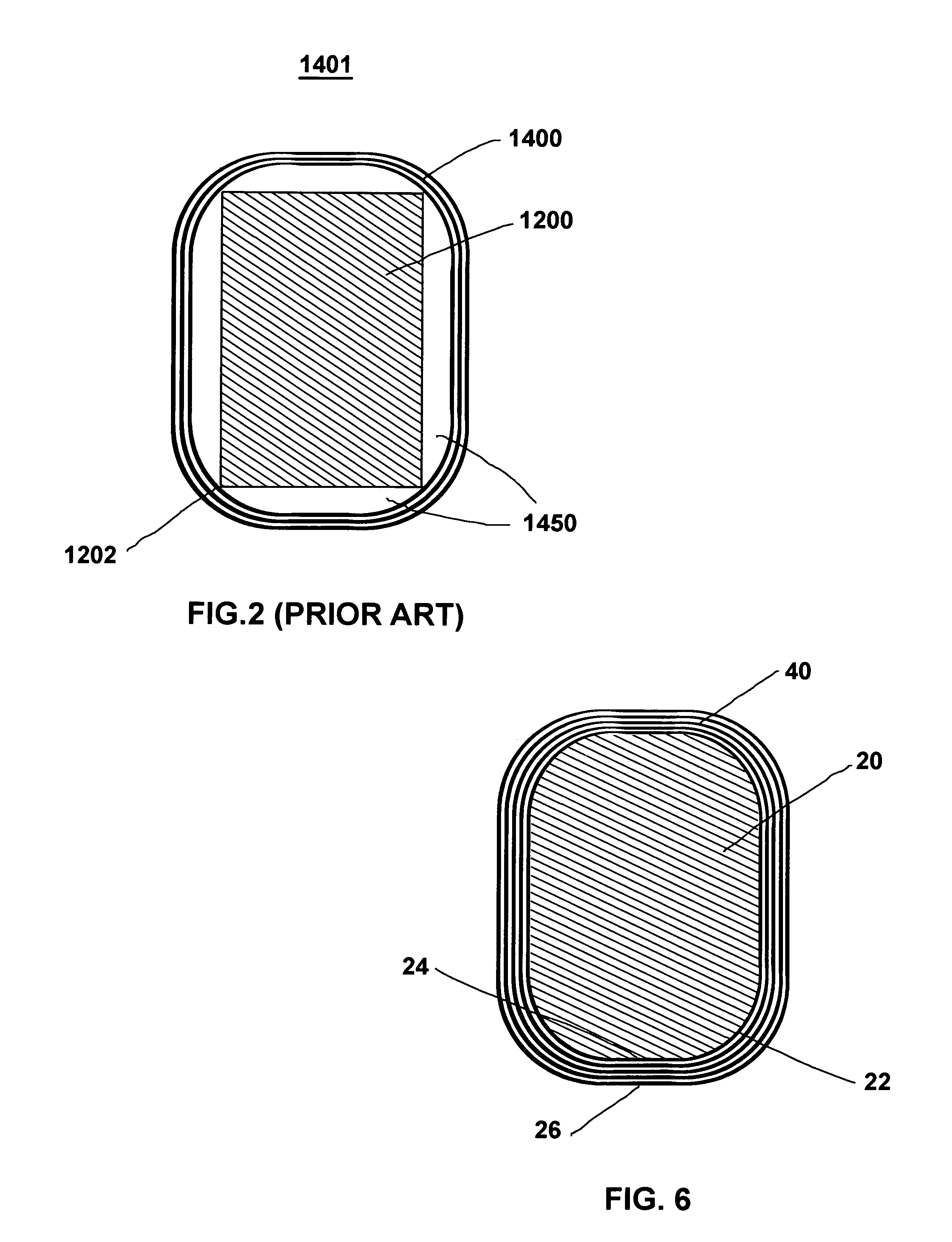
[0028]Referring now generally to FIGS. 3-8, there is shown the stator and rotor assemblies of a motor / generator 100 in accordance with the present invention. Referring more specifically to FIG. 3, there is shown a stator flux ring 10, constructed of powder metal, a plurality of separate powder metal cores 20 wound as individual electromagnets and positioned immediately adjacent to and in contact with the stator flux ring 10, and a like plurality of shoes 30 also constructed of powder metal to diffuse the magnetic flux field produced by each of the electromagnets. The powder metal stator flux ring 10, powder metal cores 20, and powder metal shoes 30 are not fabricated as a single component, as in the case of prior art motor 1000 of FIG. 1, but as separate components to facilitate their manufacture using molds and presses and to facilitate machine winding of the cores 20 to form electromagnets. The stator flux ring 10 provides a path for the magnetic flux field between the electromagn...


PUM


Abstract

A radial flux permanent magnet AC motor / generator employs a flat circular stator plate having a plurality of separately-formed electromagnets mounted in a ring pattern on a top surface thereof. A circular flux ring fabricated of powdered metal is mounted to the stator plate outside the ring of electromagnets. A plurality of permanent magnets are mounted in a ring pattern on the outer cylindrical surface of a steel rotor. The stator plate and rotor are axially and diametrically aligned such that the ring of permanent magnets rotates in close proximity to and inside the ring of electromagnets. The electromagnets utilize powder metal cores shaped to have rounded corners and flat sides that permit the use of heavier gauge windings and eliminate the air gaps that exist between the core and windings of prior art electromagnets.

Description

BACKGROUND AND SUMMARY OF THE INVENTION[0001]This invention relates generally to permanent magnet motors and generators and, more particularly, to a highly efficient sealed AC radial flux motor / generator having a ring of permanent magnets mounted on the cylindrical surface of an inner rotor and having a ring of electromagnets mounted on an outer stator such that outwardly facing surfaces of the permanent magnets rotate in close proximity to the inwardly facing surfaces of the ring of electromagnets.[0002]Variable speed electric motors of different types have been employed in a variety of applications over the years, most recently in electric vehicles. One such motor is the series DC motor, which employs brushes and wound coils. These motors suffer from low peak power densities. Thus, they are heavy and unresponsive; they are not sealed since air flow through the motor is required to cool the rotor; and they cannot run in reverse. Furthermore, their speed is difficult to control unde...

Claims


Application Information

Patent Timeline
Patent Type & Authority Patents(United States)
IPC IPC(8): H02K1/14
CPCH02K1/148H02K1/278H02K3/522H02K9/22H02K9/19H02K9/227H02K9/223H02K9/197
Inventor HOPKINS, THOMAS H.BRIES, NICHOLAS R.GRAHAM, SCOTT T.HENDRICKS, HOWARD F.STOEVER, PATRICK J.
Owner PATENT LICENSORS
Why Eureka
Try Eureka