Cell and module processing of semiconductor wafers for back-contacted solar photovoltaic module

a solar photovoltaic module and semiconductor technology, applied in the field of cell and module processing of semiconductor wafers for back-contact solar photovoltaic modules, can solve the problem of low photovoltaic efficiency of solar cells as compared to wafers

Active Publication Date: 2014-10-14
REC SOLAR
View PDF17 Cites 1 Cited by
  • Summary
  • Abstract
  • Description
  • Claims
  • Application Information

AI Technical Summary

Benefits of technology

The invention relates to a new structure for solar cells that improves their conversion efficiency. The cells have back side electric contacts made of many small fingers and ribbons that create short current paths with high surface area to minimize resistive losses and low contact areas with the semiconductor to minimize recombination of charges. When a solar module is exposed to changes in temperature and other factors, a strain relief structure in the ribbons helps to prevent stress or fracture of the cell interconnects or ribbons. This new structure makes solar cells more robust and reliable.

Problems solved by technology

The drawback of this technology is low photovoltaic efficiencies of the solar cells as compared to wafer based monocrystalline solar cells.

Method used


Image

  • Cell and module processing of semiconductor wafers for back-contacted solar photovoltaic module
  • Cell and module processing of semiconductor wafers for back-contacted solar photovoltaic module
  • Cell and module processing of semiconductor wafers for back-contacted solar photovoltaic module

Examples


first example embodiment

[0109]The first example embodiment employs a set of M solar cells laid out in a rectangular pattern of k columns and 1 rows, i.e. the number n of solar cells in the module becomes n=k·l. The example embodiment is illustrated with k=l=2, but may have any even number n of cells.

[0110]Each solar cell of the module is made from a quadratic silicon wafer of 125 mm in length and width, and which are laminated onto a front module front glass with a gap or relative distance between their respective side edges of approx. 0.2 mm. Each wafer is made by epitaxial growth of three monocrystalline silicon layers onto a porous release layer of a silicon donor wafer. The first epitaxially deposited layer is the emitter layer and is made to be 0.8 μm thick and doped to a concentration of 1·1019 cm−3 of phosphorous atoms (N-type doping), the second epitaxially deposited layer is the base layer and is made to be 40 μm thick and doped to a concentration of 3·1016 cm−3 of boron atoms (P-type doping), whi...

second example embodiment

[0123]The second example embodiment is a variant of the first example embodiment including the following steps:

[0124]1. Texturing the front side followed by diffusion with dopant and formation of an anti-reflection coating to front side of wafer. The front surface is optionally diffused or implanted to form a front surface field or floating junction. Front and back diffusions may be of the same type to achieve a floating junction at the front of the cell, or different types such that a p-n junction is formed at the back side of the cell and a front surface field is formed at the front of the cell. The resulting structure is shown in FIG. 8a).

2. Selectively removing regions of the rear-surface emitter by either:[0125]2.1 a) Coating back side of wafers with etch resist (for example Novolac resin), or optionally screen printing patterned resin and skip inkjet (FIG. 8b).[0126]b) Patterning resist using basic solution (inkjet print), optionally screen printing basic solution to pattern r...


PUM


Abstract

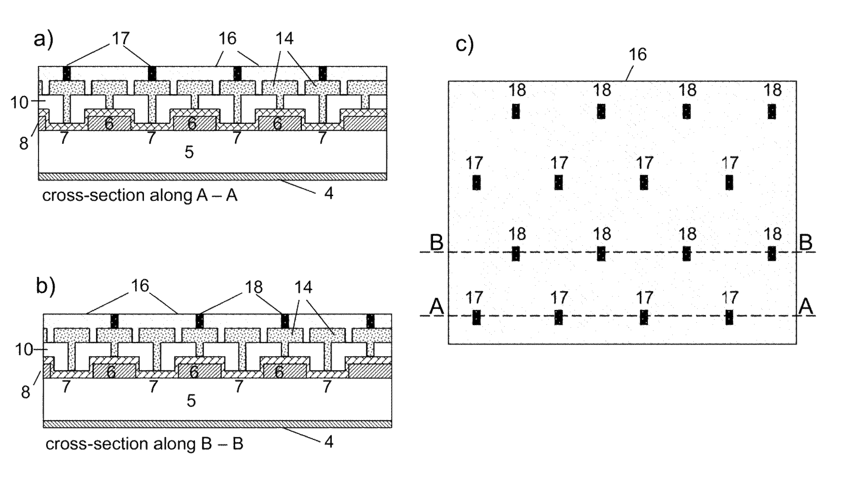
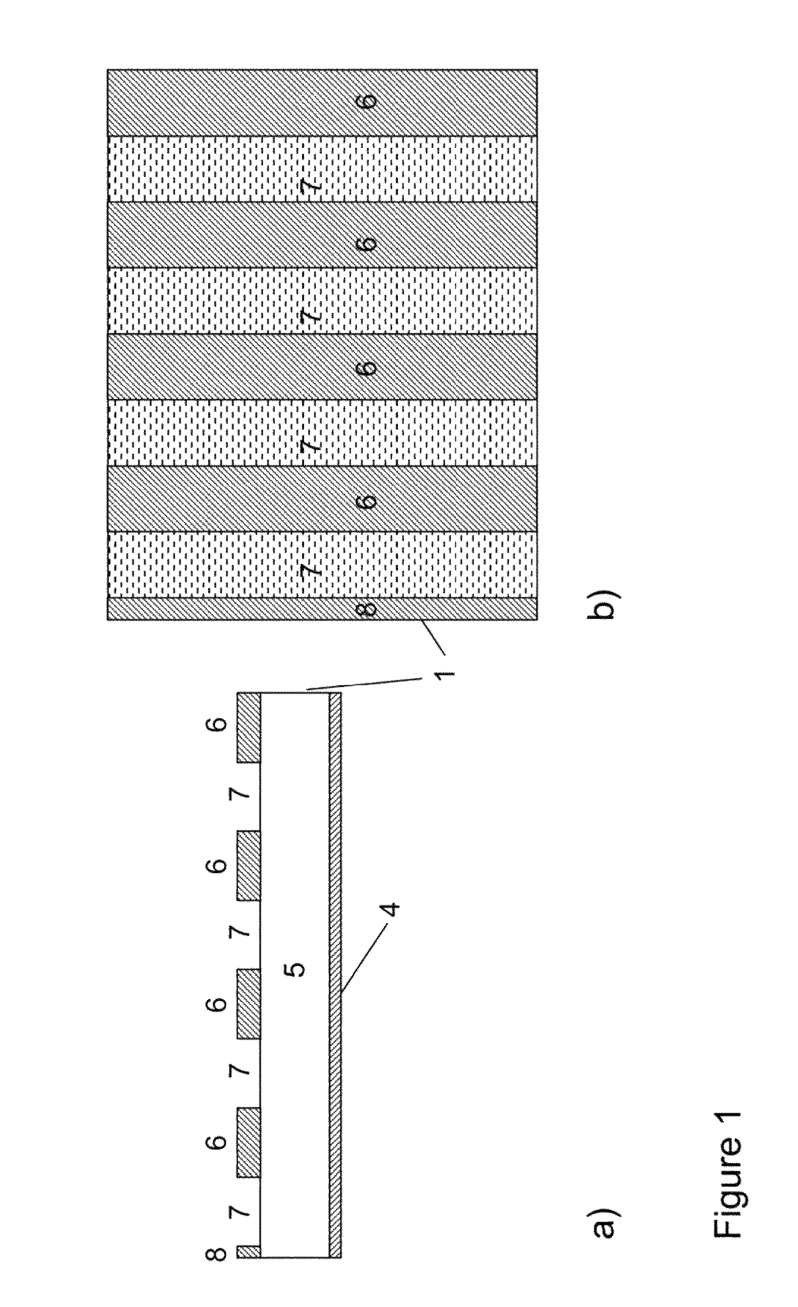
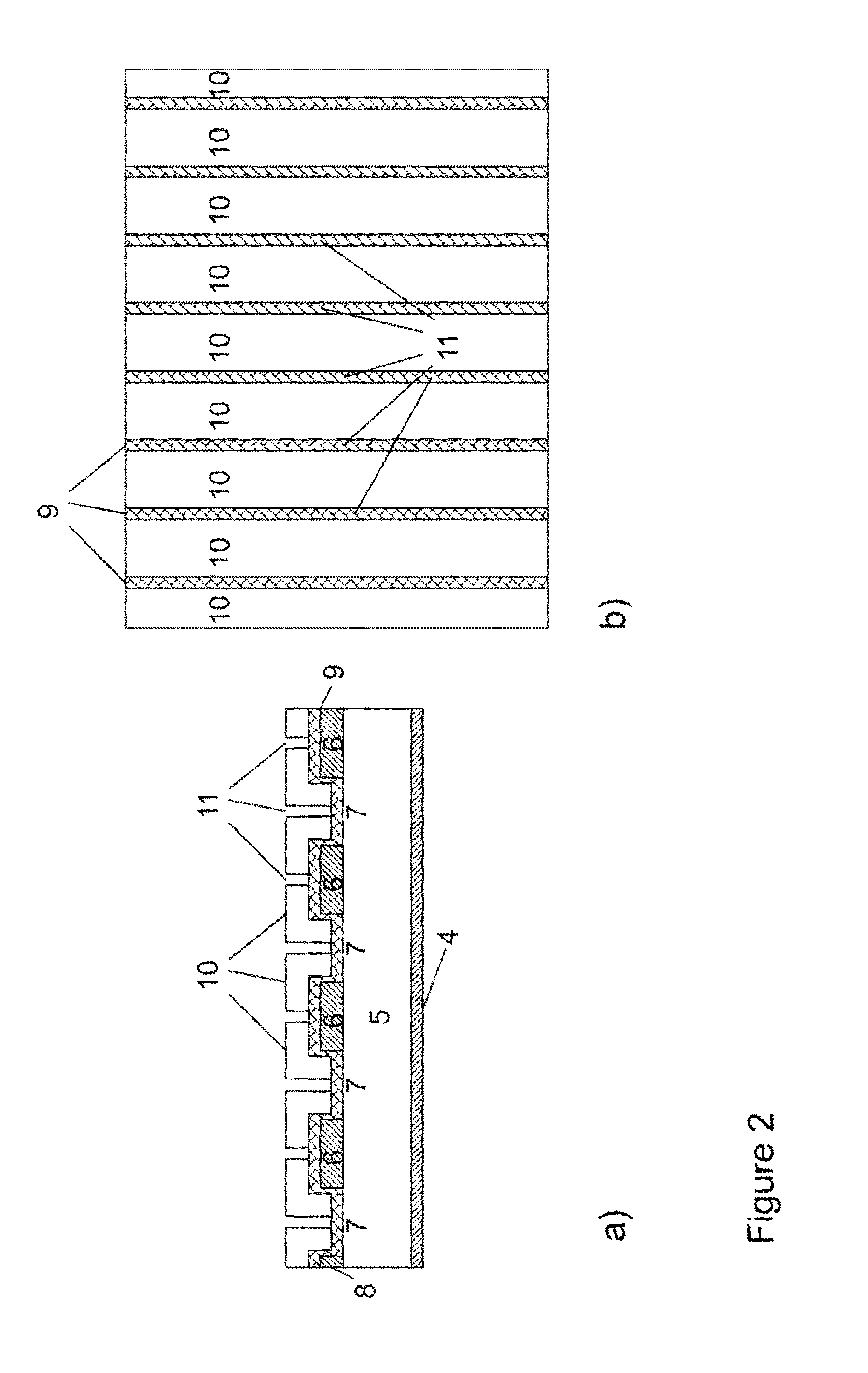
The present invention relates to cost effective production methods of high efficiency silicon based back-contacted back-junction solar panels and solar panels thereof having a multiplicity of alternating rectangular emitter- and base regions on the back-side of each cell, each with rectangular metallic electric finger conductor above and running in parallel with the corresponding emitter- and base region, a first insulation layer in-between the wafer and finger conductors, and a second insulation layer in between the finger conductors and cell interconnections.

Description

CROSS REFERENCE TO RELATED APPLICATIONS[0001]This non-provisional application claims the benefit of U.S. Provisional Application Nos. 61 / 612,724, 61 / 612,746, 61 / 612,769, and 61 / 612,800 all of which were filed on Mar. 19, 2012. The entire contents of all of the above applications are hereby incorporated by reference.FIELD OF THE INVENTION[0002]The present invention relates to cost effective production methods of high efficiency silicon based back-contacted back-junction solar panels and solar panels made by the method.BACKGROUND[0003]There are raised many concerns that the use of fossil energy is increasing the earth greenhouse effect to an extent that may turn dangerous. Thus the present consumption of fossil fuels should preferably be replaced by energy sources / carriers that are renewable and sustainable for our climate and environment.[0004]One such energy source is solar light, which irradiates the earth with vastly more energy than the present and any foreseeable increase in hum...

Claims


Application Information

Patent Timeline
Patent Type & Authority Patents(United States)
IPC IPC(8): H01L21/00H01L31/0224H01L31/048H01L31/05H01L31/068H01L31/18
CPCH01L31/1804H01L31/022441H01L31/0682H01L31/0516H01L31/0488Y02E10/547
Inventor SEWELL, RICHARD HAMILTONBENTZEN, ANDREAS
Owner REC SOLAR
Why Eureka
Try Eureka