Method for metallization or metallization and interconnection of back contact solar cells

a solar cell and back contact technology, applied in the field of metallization or metallization and interconnection of back contact solar cells, can solve the problem of low photovoltaic efficiency of solar cells as compared to wafers

Active Publication Date: 2013-09-19
REC SOLAR
View PDF10 Cites 28 Cited by
  • Summary
  • Abstract
  • Description
  • Claims
  • Application Information

AI Technical Summary

Problems solved by technology

The drawback of this technology is low photovoltaic efficiencies of the solar cells as compared to wafer based monocrystalline solar cells.

Method used


Image

  • Method for metallization or metallization and interconnection of back contact solar cells
  • Method for metallization or metallization and interconnection of back contact solar cells
  • Method for metallization or metallization and interconnection of back contact solar cells

Examples


first example embodiment

of the Ribbon Geometry

[0147]The first example embodiment of the ribbon geometry is illustrated in FIG. 8a), which in the upper part shows two arbitrarily chosen solar cells 1 number n and n+1 in one row of the solar module. For the cause of clarity the other solar cells 1 in this row (nor in the other rows) are not shown on the figure, and all details related to the solar module are omitted. The Figure does however indicate the underlying finger conductors 14 of the solar cells by the rectangles drawn with a dotted line, and the access openings 17, 18 are shown as dark squares.

[0148]The ribbons 20, 21 of this example embodiment are all rectangular with a constant cross-section and made to span across two sideways adjacent cells in the row, with an exception for the ribbons obtaining contact with either the emitter regions or the base regions of the first or last solar cell in each row. These ribbons will only span one cell. The figure illustrates the span across two cells by showing...

second example embodiment

of the Ribbon Geometry

[0152]The second example embodiment of the ribbon geometry is illustrated in FIG. 9, and is similar to the first example embodiment except for employing a discontinuous second insulation layer 16 and forming the access openings 17, 18 areas not covered by the second insulation layer.

[0153]The discontinuous second insulation layer is formed by screen printing rectangular areas of the insulation layer in a pattern as shown in the lower part of FIG. 9. The access openings 17, 18 are then located between adjacent rectangular sections of the insulation layer 16 as shown in the upper part of FIG. 9. The formation technique is the same as in the first example embodiment.

third example embodiment

of the Ribbon Geometry

[0154]The third example embodiment of the ribbon geometry is an example of using non-rectangular finger conductors and ribbons.

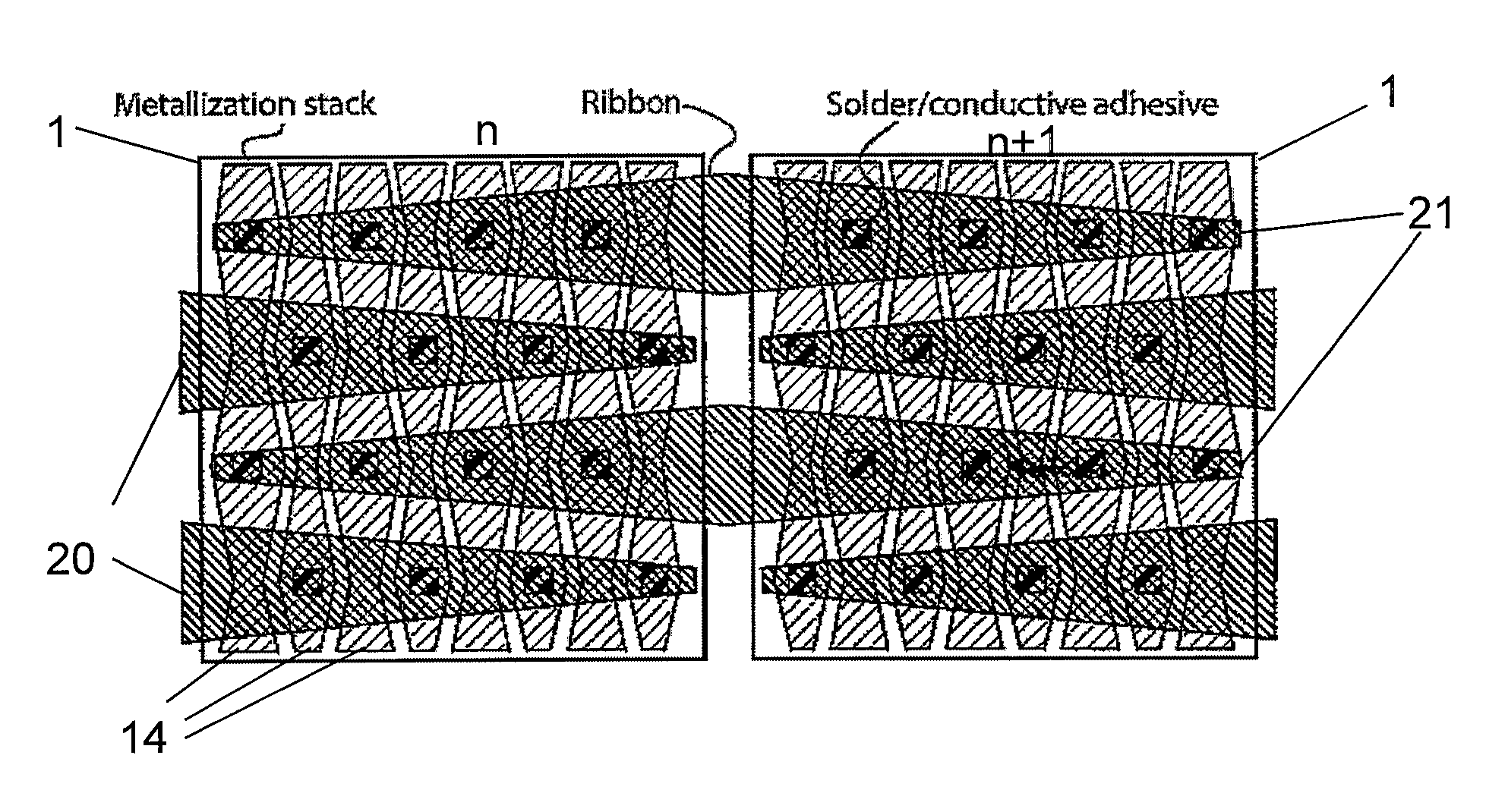
[0155]The finger conductors 14 are given a wave-resembling design by employing a zigzagged opening 13 between the finger conductors. The second insulation layer 16 is formed by depositing adhesive strips of insulating material configured as i.e. shown in the lower part of FIG. 10. The via contacts 17, 18 are made by stencil printing solder paste at onto areas of the wave-shaped finger conductors protruding outside the area covered by these adhesive strips. The ribbons 20, 21 are tapered in order to be widest in the sections where most current will be flowing in order to reduce the electric resistivity in the ribbons.

[0156]The thicknesses and materials employed in the finger conductors and ribbons are similar to the first example embodiment.


PUM


Abstract

The present invention relates to cost effective methods for metallisation and or metallisation and interconnection of high efficiency silicon based back-contacted back-junction solar panels and solar panels thereof having a multiplicity of alternating rectangular emitter- and base regions on the back-side of each cell, each with rectangular metallic electric finger conductor above and running in parallel with the corresponding emitter- and base region, a first insulation layer in-between the wafer and finger conductors, and a second insulation layer in between the finger conductors and cell interconnections.

Description

[0001]The present disclosure relates to methods for forming contacts and interconnections between photovoltaic cells (PV cells).BACKGROUND[0002]There are raised many concerns that the use of fossil energy is increasing the earth greenhouse effect to an extent that may turn dangerous. Thus the present consumption of fossil fuels should preferably be replaced by energy sources / carriers that are renewable and sustainable for our climate and environment.[0003]One such energy source is solar light, which irradiates the earth with vastly more energy than the present and any foreseeable increase in human energy consumption. However, solar cell electricity has up to date been too expensive to be competitive with nuclear power, thermal power, hydroelectric power etc. This needs to change if the vast potential of the solar cell electricity is to be realised.[0004]The cost of electricity from a solar panel is a function of the energy conversion efficiency and the production costs of the solar ...

Claims


Application Information

Patent Timeline
Patent Type & Authority Applications(United States)
IPC IPC(8): H01L31/05H01L31/0224H01L31/048H01L31/20
CPCH01L31/022441H01L31/0488Y02E10/547H01L31/0682H01L31/1804H01L31/0516
Inventor SEWELL, RICHARD HAMILTONLYON, ALAN FRANCISBENTZEN, ANDREAS
Owner REC SOLAR
Why Eureka
Try Eureka