Method and equipment for forming multi-focusing images

A multi-focus, image technology, applied in the direction of image communication, electrical components, etc., can solve time-consuming problems

Active Publication Date: 2006-12-20
FFEI LTD
View PDF1 Cites 24 Cited by
  • Summary
  • Abstract
  • Description
  • Claims
  • Application Information

AI Technical Summary

Problems solved by technology

The problem with this method is that for small depths of focus over the range of sample foc...

Method used


Image

  • Method and equipment for forming multi-focusing images
  • Method and equipment for forming multi-focusing images
  • Method and equipment for forming multi-focusing images

Examples


Embodiment Construction

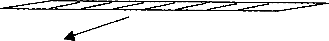
[0072] Standard line scanning involves a single row x pixel array, each pixel typically corresponding to a detector in the array. For color, a single row is provided for each of the three colors (eg red green blue). The single row is then traversed in a direction perpendicular to the detector array rows. The traverse speed is set to traverse the detector a distance of one pixel in the scan direction after one "line time" of the detector so that the next line time produces a row of pixels adjacent to the previous row. this is in image 3 As shown in , the 1D array is scanned along the direction indicated by the arrow in the figure.

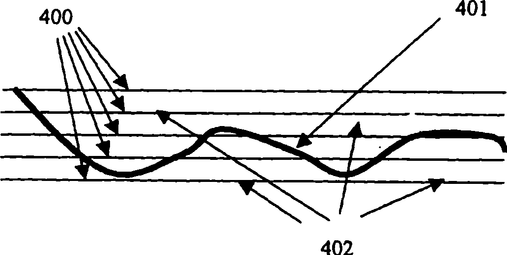
[0073] Figure 4 is the perspective layout of the 1D array scan seen from the tail of the 1D array. The direction of traverse is indicated by an arrow, where the first scan line is marked with a "1", the second line with a "2", and so on. The simplest embodiment is to scan and adjust the focus to a different focus stack position during the mov...


PUM


Abstract

The present invention provides a method for producing targeted multiple focus pile images, which comprises the steps of utilizing relative scanning movement between targeted and photodetector arrays, receiving repeatedly the image information of the scanning lines, transforming the relative focusing between the targeted and arrays, thus obtaining each images in the pile.

Description

technical field [0001] The present invention relates to methods and apparatus for forming multi-focus stack images. Background technique [0002] In some market areas such as medical applications, samples are examined using a microscope and a digital image is generated using a two-dimensional digital camera attached to the microscope. The observed sample captured by the digital camera is limited in area. For a 40x objective, the typical area is only 0.7mm wide. Given an active area of ​​64 x 24 mm on a microscope slide, the possible sample area is only a very small area. One approach to this is to step and repeat over the entire sample area, also known as macro dithering. A more preferred process is to use a line scanning unit similar to that disclosed in US 6,711,283, where 0.7 x 64 mm strips of data can be collected. Adjacent strips can then be scanned so that the images can be stitched or stitched together, as described in patent GB2206011. [0003] One problem with ...

Claims


Application Information

Patent Timeline
IPC IPC(8): H04N1/191
Inventor 菲利普·M.·戈什
Owner FFEI LTD
Why Eureka
Try Eureka