Multi-antenna receiving apparatus, multi-antenna receiving method, multi-antenna transmitting apparatus, and multi-antenna communication system

A technology for receiving devices and sending devices, which is applied in diversity/multi-antenna systems, multi-frequency code systems, multiplex communication, etc., and can solve problems such as complex structures of receiving devices

Active Publication Date: 2006-12-20
INTERDIGITAL PATENT HLDG INC
View PDF6 Cites 23 Cited by
  • Summary
  • Abstract
  • Description
  • Claims
  • Application Information

AI Technical Summary

Problems solved by technology

[0017] However, in a multi-antenna system such as Non-Patent Document 2, although the data commun

Method used


Image

  • Multi-antenna receiving apparatus, multi-antenna receiving method, multi-antenna transmitting apparatus, and multi-antenna communication system
  • Multi-antenna receiving apparatus, multi-antenna receiving method, multi-antenna transmitting apparatus, and multi-antenna communication system
  • Multi-antenna receiving apparatus, multi-antenna receiving method, multi-antenna transmitting apparatus, and multi-antenna communication system

Examples


Embodiment approach 1

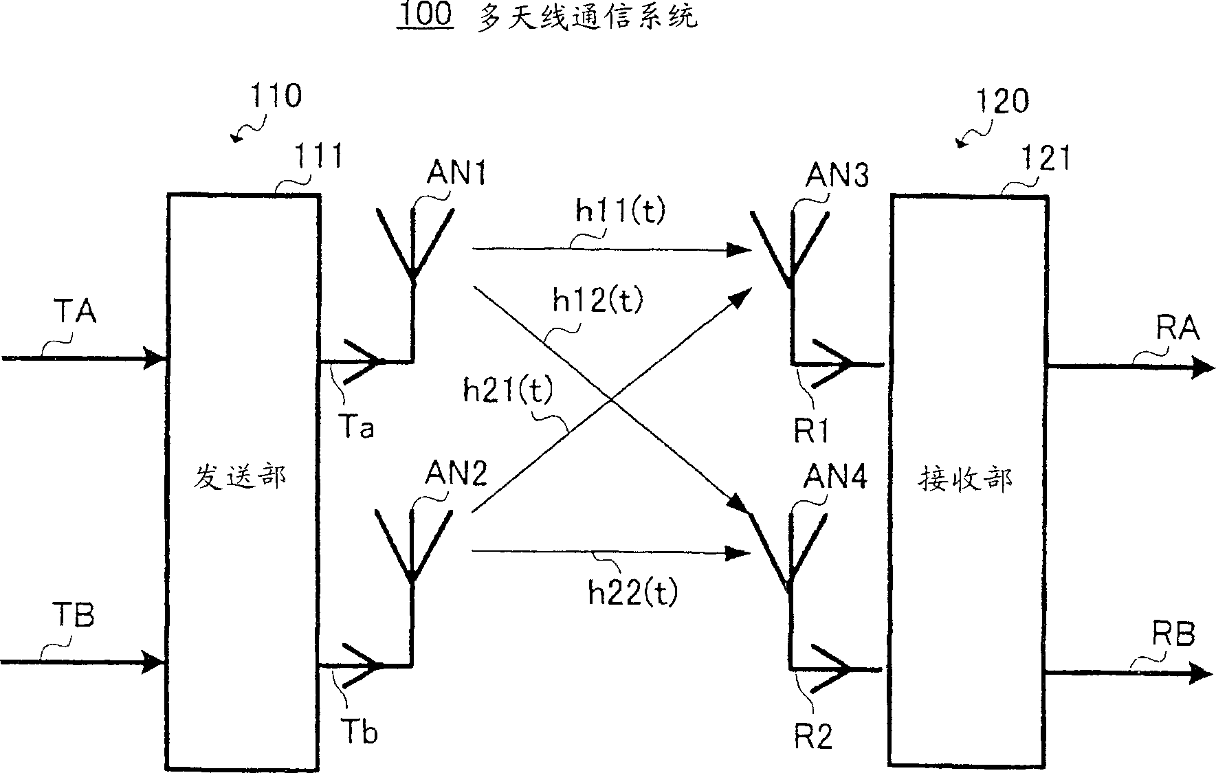
[0172] figure 1 The overall configuration of the multi-antenna communication system described in this embodiment is shown. In this embodiment, in order to simplify the description, the case where there are two transmitting antennas and two receiving antennas is described, but it is applicable to M (M≥2) transmitting antennas and N (N≥2) receiving antennas. Antennas for multi-antenna systems.

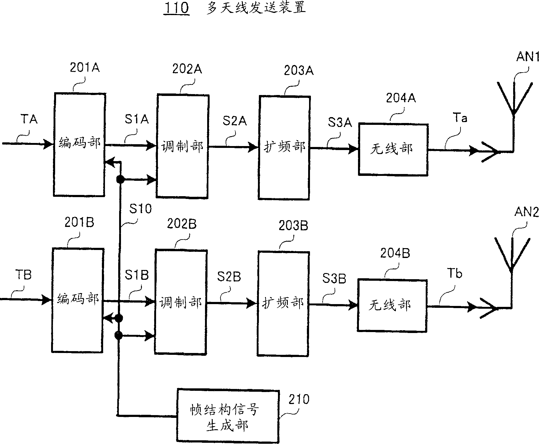
[0173] The multi-antenna transmission device 110 of the multi-antenna communication system 100 obtains the modulated signals Ta and Tb by performing predetermined modulation processing and conversion processing to radio frequency on the respective transmission digital signals TA and TB in the transmission unit 111, and transmits them from the antennas AN1 and AN2 to send. The multi-antenna reception device 120 inputs reception signals R1 and R2 received by the respective antennas AN3 and AN4 to the reception unit 121 . The receiving section 121 obtains received data RA and RB correspo...

Embodiment approach 2

[0217] In this embodiment, a configuration is proposed in which a portion for performing dummy determination for reducing candidate signal points is simpler than in Embodiment 1, so that received data with a better error rate characteristic can be obtained with a simpler configuration. Multi-antenna receiver.

[0218] exist Figure 12 in, right with Figure 5 Corresponding parts are denoted by the same reference numerals, and show the configuration of the signal processing unit 1200 of the multi-antenna reception device in this embodiment. exist Figure 12 The signal processing section 1200 with Figure 5 Compared with the signal processing unit 404 of the present invention, the soft decision unit 506 ( Figure 5 ). Then, the reception data RB of the modulated signal B obtained by the soft decision unit 518 is input to the signal point reduction units 1201 and 1202 . The signal point reduction units 1201 and 1202 use the received data RB obtained by the soft decision uni...

Embodiment approach 3

[0223] In this embodiment, in addition to reducing candidate signal points and performing main judgment to obtain received data with good error rate characteristics with a small number of calculations, it is also proposed to further improve error rate characteristics through the application of iteration technology. multi-antenna receiver.

[0224] exist Figure 13 , right with Figure 5 Corresponding parts are assigned the same reference numerals, and show the configuration of the signal processing unit 1300 of the multi-antenna reception device in this embodiment. That is, the signal processing section 1300 is used to replace Figure 4 The signal processing unit 404 is used in the multi-antenna receiving device 120 .

[0225] described in Embodiment 1 Figure 5 The difference between the signal processing unit 404 and the signal processing unit 1300 of this embodiment is that the signal point reduction units 1301 and 1302 receive input from the soft determination unit 518 i...


PUM


Abstract

Soft decision parts (503,506) perform temporary decisions of modulated signals (502,505) as separated by a separating part (501) using an inverse matrix calculation of a channel scatter matrix. Signal point reduction parts (508,510,514,516) use the temporary decision results (504,507) to reduce the number of candidate signal points of multiplexed modulated signals. Soft decision parts (512,518) use the candidate signal points as reduced to perform precise decisions, thereby obtaining reception data of the modulated signals (RA,RB). In this way, a smaller number of calculations is used to successfully obtain the reception data (RA,RB) having an improved error rate characteristic without degradation of the data transmission efficiency.

Description

technical field [0001] The present invention relates to a multi-antenna receiving device, a multi-antenna receiving method, a multi-antenna sending device and a multi-antenna communication system, in particular to a method of using multiple antennas to receive different modulated signals simultaneously transmitted from multiple antennas at the transmitting end, from the A technique for restoring transmission data corresponding to each modulated signal from a received signal formed by multiplexing a plurality of modulated signals on a propagation path. Background technique [0002] In the past, there was a technique like a communication method called MIMO (Multiple-Input Multiple-Output), by separately modulating multiple sequences of transmission data and simultaneously transmitting each modulated data from multiple antennas, To increase the data communication speed. Multiple antennas are used at the receiving end to receive transmission signals from multiple antennas. [...

Claims


Application Information

Patent Timeline
IPC IPC(8): H04J15/00H04L27/00H04J99/00H04B7/08H04L1/06H04L27/26
CPCH04B7/0413H04B7/0851H04L1/06H04L27/2647H04L1/0057H04L1/0071H04L1/0086H04L1/0618H04L1/1819H04L25/03229H04L2025/03414H04L25/03305H04L25/03324H04L25/03891H04L2025/03611H04L5/0023H04L27/26524H04L27/2634
Inventor 村上丰小林圣峰折桥雅之松冈昭彦今村大地拉休尔·马利克
Owner INTERDIGITAL PATENT HLDG INC
Why Eureka
Try Eureka