Gearbox circuit for changing data bit width in high-speed transceiver and working method thereof

A gearbox circuit and data bit width technology, applied in the direction of asynchronous pulse counters, etc., can solve the problems of reducing system transmission efficiency and failing to meet system requirements

Active Publication Date: 2016-09-14
58TH RES INST OF CETC
View PDF6 Cites 0 Cited by
  • Summary
  • Abstract
  • Description
  • Claims
  • Application Information

AI Technical Summary

Problems solved by technology

This method is only suitable for FPGA design, because FPGA users can design the control logic by themselves
In general ASIC or SOC design, this method of significantly reducing system transmission efficiency cannot meet system requirements.

Method used


Image

  • Gearbox circuit for changing data bit width in high-speed transceiver and working method thereof
  • Gearbox circuit for changing data bit width in high-speed transceiver and working method thereof
  • Gearbox circuit for changing data bit width in high-speed transceiver and working method thereof

Examples


Embodiment Construction

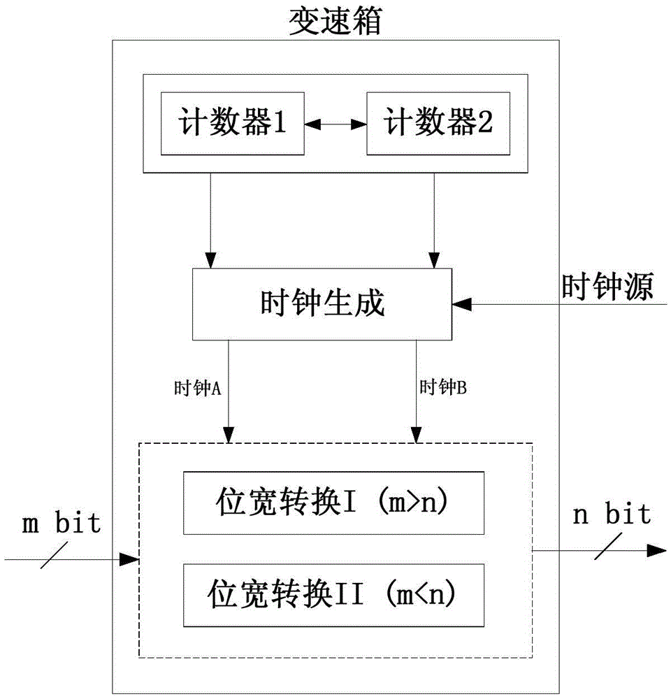
[0062] The present invention will be further described below in conjunction with the drawings and specific embodiments. In the present invention, according to the principle of stable bit rates at both ends of the gearbox, and according to the bit width relationship between input data and output data, a high-speed clock source is used to obtain two synchronous clocks to control the input and output of gearbox data. This method does not require any processing or control of the input data, and can perform continuous data transmission without changing the data bit width. It is possible to switch from more to less data bit width or from less to more under the condition of keeping input and output continuously without suspending input data. Gearbox circuit structure such as figure 1 As shown, it includes a counter generation circuit, a clock generation circuit, a first data width conversion circuit, and a second data width conversion circuit. The output of the counter generation ci...


PUM


Abstract

The invention relates to a gearbox circuit for changing data bit widths in a high-speed transceiver and a working method of the gearbox circuit. Conversion between different data bit widths is controlled by controlling generation of a clock used for data input and a clock used for data output and the phase relation between the two clocks, and then data bit width matching between internal modules is achieved. The gearbox circuit comprises a counter generation circuit, a clock generation circuit, a first data width conversion circuit and a second data width conversion circuit. The output of the counter generation circuit is connected with the clock generation circuit, the input of the clock generation circuit is connected with a clock source, and the output of the clock generation circuit is connected with the first data width conversion circuit and the second data width conversion circuit. The gearbox circuit and the working method have the advantages that under the conditions that the data transmission bit rate is not affected, and data transmission efficiency is not reduced, conversion of the data bit widths can be conducted at will, and the gearbox circuit and the working method are suitable for the design method and the circuit in the gearbox circuit field with any chip design.

Description

technical field [0001] The invention relates to a circuit and a method for realizing arbitrary change of the data bit width, in particular to a gearbox circuit for changing the data bit width in a high-speed transceiver and its working method. Background technique [0002] With the development of serial communication rate to 10Gbps or even 100Gbps, traditional low-efficiency codecs such as 8b / 10b, due to their bandwidth waste rate of up to 20%, continue to use such coding methods in high-speed systems, which will greatly waste channels The bandwidth reduces the data transmission efficiency. Therefore, some high-efficiency encoding methods such as 64B / 66B, 64B / 67B, etc. are more common in the current high-speed system design. However, most of the current digital system bus bit widths are 1, 2, 4, 8, etc. 2 to the power of n bytes. For example, in the physical layer standard of 10G-WIS, the data sent from the upper layer protocol first It needs to be encoded by 64B / 66B, and ...

Claims


Application Information

Patent Timeline
Patent Type & Authority Patents(China)
IPC IPC(8): H03K23/58
Inventor 周昱雷淑岚魏敬和
Owner 58TH RES INST OF CETC
Why Eureka
Try Eureka