Three-phase wound core and three phase transformer
A technology for winding iron cores and iron cores, applied in the direction of transformer/inductor magnetic cores, etc., can solve the problems of increasing the number of manufacturing processes and increasing the size of manufacturing equipment, and achieve the effect of reducing the amount of use
- Summary
- Abstract
- Description
- Claims
- Application Information
AI Technical Summary
Problems solved by technology
Method used
Image
Examples
Embodiment 1
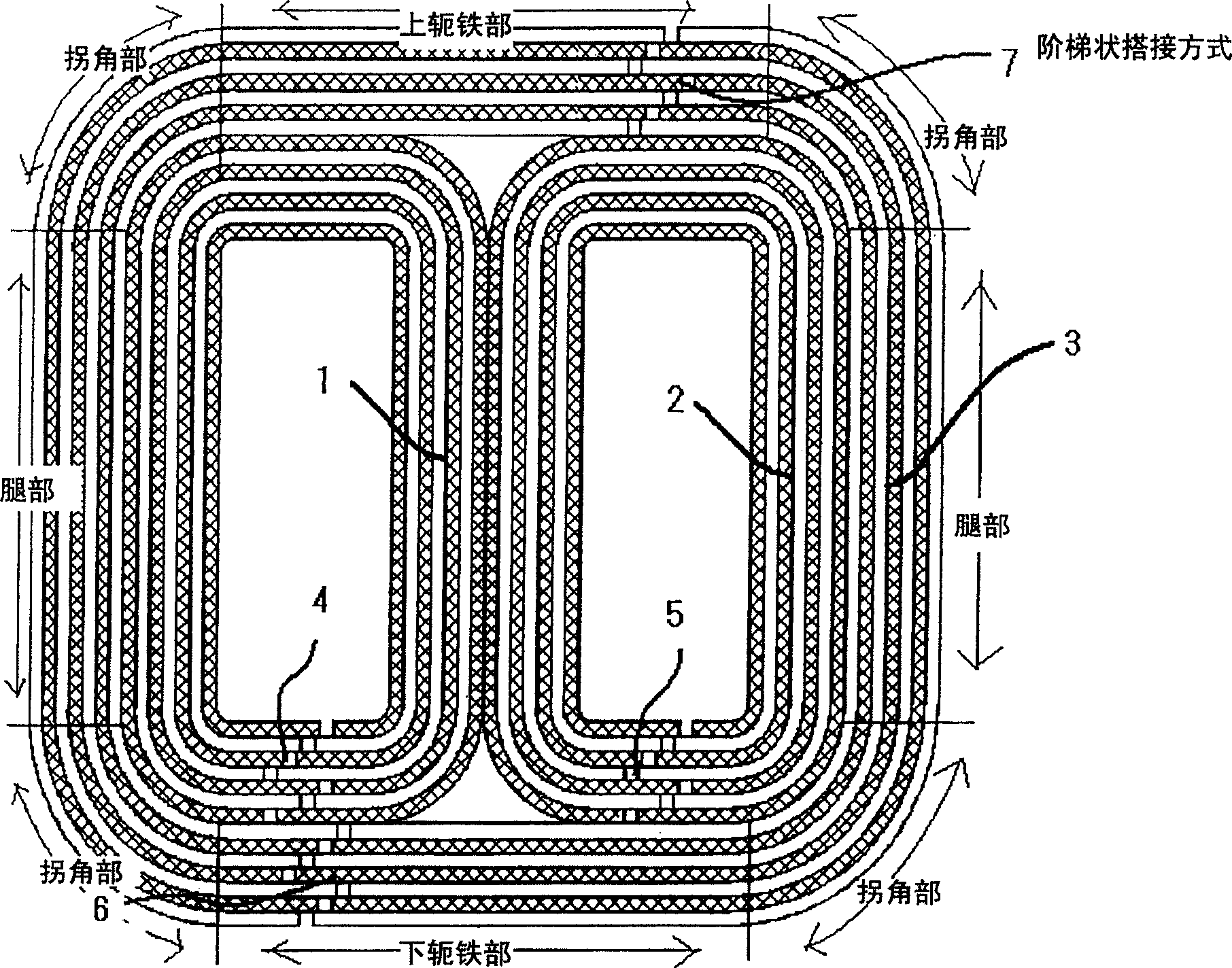
[0036] figure 1 Shows the first embodiment of the present invention. Such as figure 1 As shown, the three-phase wound core is composed of a first inner core 1 , a second inner core 2 and an outer core 3 . Because the core magnetic flux density distribution of the transformer is concentrated in the inner core, therefore, in order to suppress the loss of the core, it is ideal to set an inner core joint 4 and an inner core joint 5 on the inner core 1 and inner core 2 respectively, instead of It splits. In addition, in the case of the inner core, since the cutting length of the silicon steel sheets is relatively short, there are no special restrictions on the manufacturing process, and one-point bonding is sufficient.
[0037] On the other hand, if the outer core is provided with one junction, the cutting length will become longer, and if it is arranged in a rectangular shape, the external dimensions will increase, and it will be easily restricted by equipment. Therefore, th...
Embodiment 2
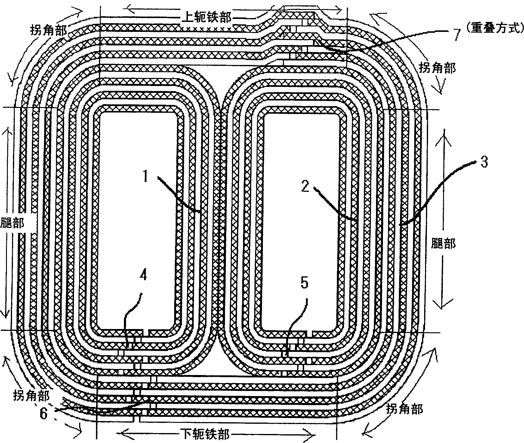
[0041] figure 2 Shows the second embodiment of the present invention. The negative lesson that the size of the joint of the outer core of the stepped lap joint shown in the first embodiment can suppress the size of the joint is that it tends to hinder the flow of magnetic flux and increase the loss of the core. Therefore, by making at least one of the joints of the outer core overlap, the loss of the core can be suppressed. figure 2 In this case, the increase in size of the transformer can be reduced by arranging the superimposed outer core connecting portion 7 on the upper yoke portion. This is because there is a gap between the upper part and the upper end of the outer core, and since terminals for connection are arranged on the upper part, the increased size of the overlapping joint can be accommodated within this size range.
Embodiment 3
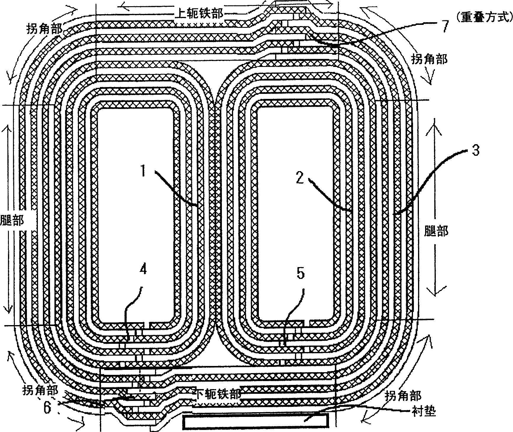
[0043] Again, if image 3 As shown, if both the upper and lower outer core joints 6 and 7 are joints in an overlapping manner, the outer core loss can be further suppressed.
[0044] Here, since the size of the connection portion of the outer core joint portion formed on the lower yoke portion becomes large, the core is unstable. For stability, it is best to pack in a pad of the same thickness as the increased size of the lower lap.
PUM
 Abstract
Description
Claims
Application Information
 - R&D
- Intellectual Property
- Life Sciences
- Materials
- Tech Scout
- Unparalleled Data Quality
- Higher Quality Content
- 60% Fewer Hallucinations
Browse by: Latest US Patents, China's latest patents, Technical Efficacy Thesaurus, Application Domain, Technology Topic, Popular Technical Reports.
© 2025 PatSnap. All rights reserved.Legal|Privacy policy|Modern Slavery Act Transparency Statement|Sitemap|About US| Contact US: help@patsnap.com


