Resonance circuit output characteristic controlling method

A resonant circuit and output characteristic technology, applied in the field of resonant circuit output characteristic control, can solve problems such as weak voltage regulation capability, affecting module performance, and inability to improve control defects.

Active Publication Date: 2006-12-27
ASTEC POWER SUPPLY (SHENZHEN) CO LTD
View PDF0 Cites 21 Cited by
  • Summary
  • Abstract
  • Description
  • Claims
  • Application Information

AI Technical Summary

Problems solved by technology

but from image 3 It can be seen from the figure that when the frequency rises to a certain level, the characteristic curve becomes very flat, and may even rise instead of falling, making the ability of the frequency change to adjust the voltage to become very weak.
For modules that need to get a wider output voltage range, it greatly affects the performance

Method used


Image

  • Resonance circuit output characteristic controlling method
  • Resonance circuit output characteristic controlling method
  • Resonance circuit output characteristic controlling method

Examples


Embodiment Construction

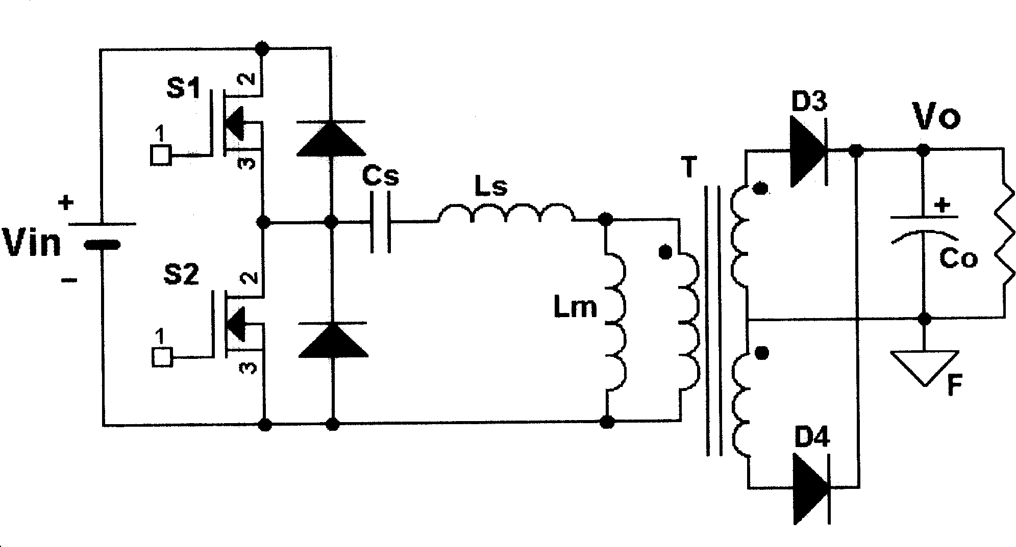
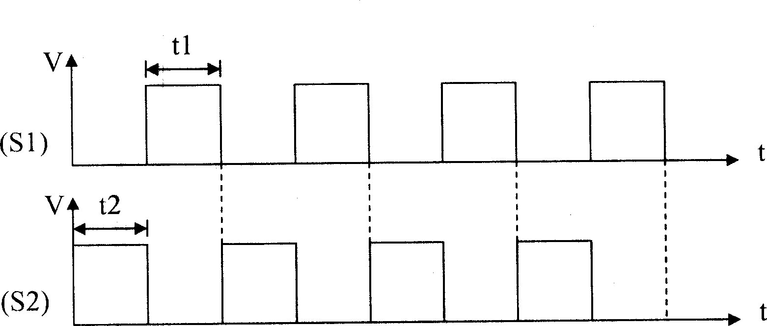
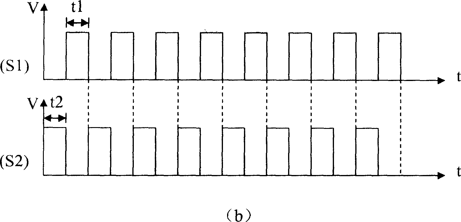
[0019] A method for controlling the output characteristics of a resonant circuit is to adjust the output voltage by comprehensively using PFM and PWM control modes to control two sets of switch tubes of the circuit, so as to improve the control of the voltage output characteristics of the resonant circuit.

[0020] still with figure 1 Take the half-bridge LLC resonant circuit in the example, Figure 4 Curve A in the figure is a schematic diagram of the characteristic curve of output voltage Vo and frequency f with a duty cycle of 50% using a separate PFM control method; Figure 4 Curves B1, B2, and B3 in the figure are schematic diagrams of the characteristic curves of the output voltage Vo and the duty cycle D when the switching frequency is 120kHz, 210kHz, and 290kHz, respectively, using a separate PWM control mode; Figure 4 The curves C1, C2, and C3 in the figure are schematic diagrams of the characteristic curves of output voltage Vo, duty cycle D, and frequency f in the...


PUM


Abstract

The disclosed output feature control method for resonant circuit comprises: with two groups of switch tubes, changing the conductive frequency for tube to adjust output voltage, and adjusting the tube duty rate; wherein, the switch point can be controlled by setting cut-in frequency or voltage. This invention brings PWM method for complementary symmetry drive to overcome the defect of PFM method, and increases adjustment capacity for output voltage.

Description

【Technical field】 [0001] The invention relates to a resonant circuit control technology, in particular to a method for controlling output characteristics of a resonant circuit. 【Background technique】 [0002] At present, the resonant circuit generally adopts a pulse frequency modulation (PFM for short) method, and the required output voltage is obtained by adjusting the switching frequency of the circuit. figure 1 It is a typical half-bridge LLC series resonant circuit, which can realize the zero-voltage turn-on of the main switch tubes S1 and S2, eliminate the reverse recovery of the output rectifier diodes D3 and D4, and improve the efficiency of the circuit. When the circuit is controlled by PFM, the two switching tubes S1 and S2 are driven complementary and symmetrically, and each is turned on for 50% of the switching period. When performing PFM control, the conduction states of S1 and S2 at different frequencies are as follows: figure 2 As shown in (a) and (b), t is ...

Claims


Application Information

Patent Timeline
IPC IPC(8): H02M3/28H02M3/335
CPCY02B70/1433Y02B70/10
Inventor 李军任曌华许峰吴宝善
Owner ASTEC POWER SUPPLY (SHENZHEN) CO LTD
Why Eureka
Try Eureka