Elevator apparatus

A technology for elevators and guiding devices, which can be used in textile cables, transportation and packaging, textiles and papermaking, etc., and can solve problems such as inability to stabilize traction

Inactive Publication Date: 2006-12-27
MITSUBISHI ELECTRIC CORP
View PDF1 Cites 6 Cited by
  • Summary
  • Abstract
  • Description
  • Claims
  • Application Information

AI Technical Summary

Problems solved by technology

[0004] When the above-mentioned conventional resin-coated rope is directly applied to a general elevator device, it ma

Method used


Image

  • Elevator apparatus
  • Elevator apparatus
  • Elevator apparatus

Examples


Embodiment approach 1

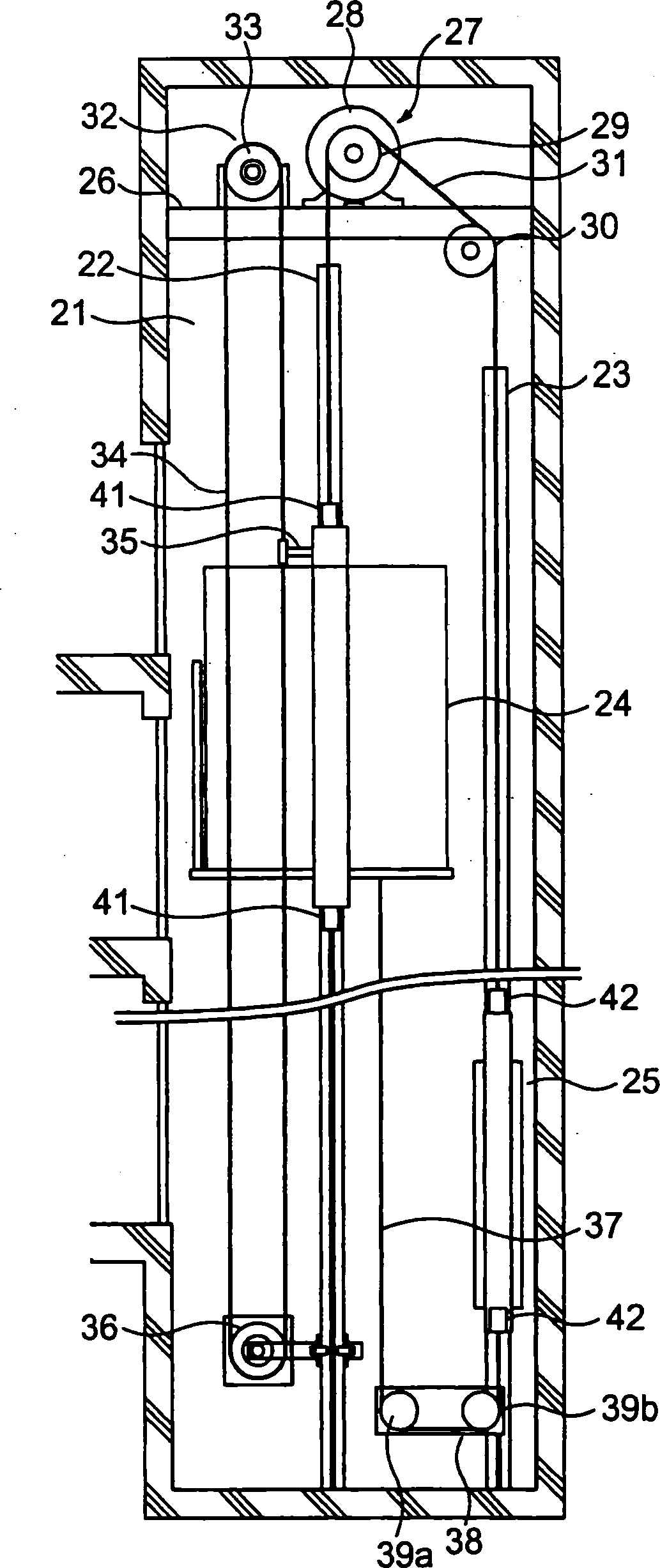
[0013] figure 1 It is a configuration diagram showing the elevator apparatus (machine-room-less elevator) according to Embodiment 1 of the present invention. In the drawing, a pair of car guide rails 22 and a pair of counterweight guide rails 23 are provided in a hoistway 21 . The car 24 moves up and down in the hoistway 21 along the car guide rail 22 . The counterweight 25 moves up and down in the hoistway 21 along the counterweight guide rail 23 .

[0014] A machine table (support beam) 26 is fixed to an upper portion in the hoistway 21 . A driving device (tractor) 27 that generates a driving force for raising and lowering the car 24 and the counterweight 25 is supported on the machine table 26 . The driving device 27 has: a driving device main body 28 including a motor and a brake; and a driving sheave 29 rotated by the driving device main body 28 . A rotatable deflector wheel 30 is installed on the machine table 26 .

[0015] A plurality of (only one is shown in the f...

Embodiment approach 2

[0044] Next, Figure 4 It is a configuration diagram showing an elevator apparatus according to Embodiment 2 of the present invention. In the figure, a counterweight balancing chain 43 is suspended between the car 24 and the counterweight 25 . The counterweight balance chain 43 has: a car-side end connected to the lower part of the car 24 ; and a counterweight-side end connected to the lower part of the counterweight 25 . Other structures are the same as those in Embodiment 1.

[0045] In this way, when the lifting stroke of the car 24 is short, the counterweight balance chain 43 can be used instead of the counterweight rope 37, and the same effect as that of the first embodiment can be obtained.

[0046] In addition, Whisperflex (registered trademark) or the like may be used instead of the counterweight rope 37 and the counterweight balance chain 43 .

[0047] In addition, in the above example, the driving device 27 is arranged in the upper part of the hoistway 21, but the...


PUM


Abstract

In an elevator apparatus, an elevator car is suspended in an elevator shaft by a main rope. The car is provided with a car guide device engaging with a car guide rail. A speed regulator sheave is provided at the upper part of the elevator shaft. A speed regulator rope is passed over the speed regulator sheave. The speed regulator rope is circulated as the car is lifted and lowered. A resin-coated rope, having on its outer periphery a coating body of a resin material, is used as the main rope and the speed regulator rope. A non-lubricated guide device is used as the car guide device.

Description

technical field [0001] The present invention relates to an elevator apparatus using, as a main rope, a resin-coated rope provided with a covering body formed of a resin material on the outer peripheral portion. Background technique [0002] The main rope of the existing elevator device is constituted by twisting a plurality of strands. Each strand is formed by twisting a plurality of steel wires. Each thread is covered with a thread sheath made of resin. Moreover, the outer peripheral part of the whole main rope is covered with the rope sheath which consists of resins (for example, refer patent document 1). [0003] Patent Document 1: Japanese Patent Laid-Open No. 2001-262482 [0004] When the conventional resin-coated rope as described above is directly applied to a general elevator apparatus, it may not be possible to stably generate a predetermined traction force due to the influence of the equipment in the hoistway. Contents of the invention [0005] The present in...

Claims


Application Information

Patent Timeline
IPC IPC(8): B66B7/04B66B7/06
CPCD07B2201/2061D07B2501/2007D07B2201/2049D07B1/0686D07B1/16B66B7/06D07B2201/2053D07B2201/1036B66B7/062D07B2201/1016D07B1/22D07B2801/24
Inventor 光井厚
Owner MITSUBISHI ELECTRIC CORP
Why Eureka
Try Eureka