

Process of grinding nozzle for impacting generator set
An impact and grinding technology, applied in the direction of machine tools suitable for grinding workpiece edges, can solve the problems of poor roughness and large deviation of coaxiality of processing technology, and achieve small roughness and small deviation of coaxiality. Effect
- Summary
- Abstract
- Description
- Claims
- Application Information
AI Technical Summary
Problems solved by technology
Method used
Image

Examples
Embodiment 1
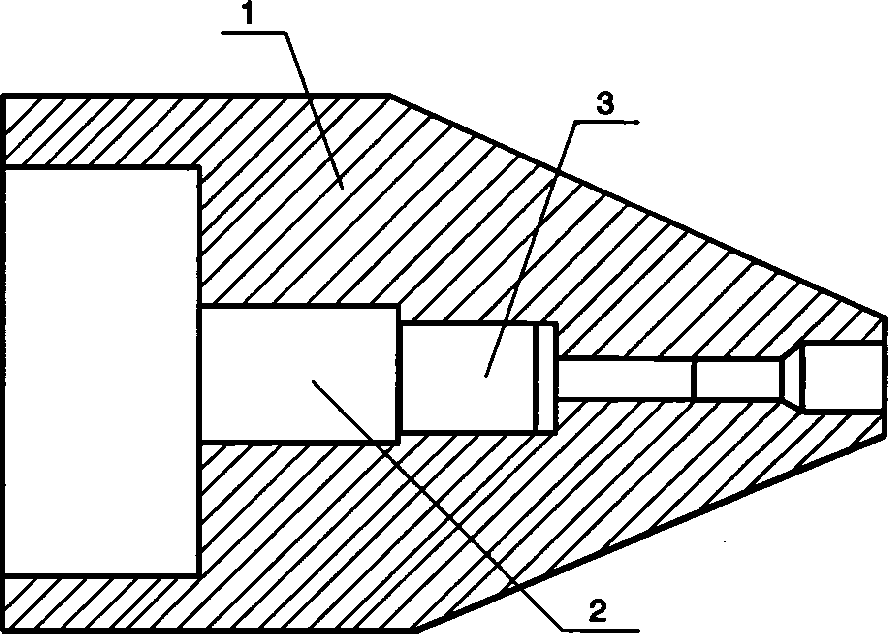
[0017] Embodiment 1: as figure 1 , the needle grinding process of the impact type unit, the product parts are based on the Φ85H8 of the needle head 1, a new mandrel 2 is used, positioned with Φ85H8, connected with M80×4 thread 3, and the center holes at both ends are used as the grinding positioning reference , the process flow is:
[0018] (1) Grind the outer circle of the mandrel Φ85 and the inner hole of the spray needle Φ85H8, take a gap of 0.02mm, wipe the inner hole and the outer circle of the mandrel with gasoline, and evenly coat a layer of butter on the outer circle of the mandrel and the thread , tighten.
[0019] (2) Grind the 60° conical surface of the inner hole of the spray needle Φ30H8 and the center hole of the mandrel with a 60° oilstone tip, and add kerosene to lubricate the surface roughness of the two center holes to Ra0.2μm, and the two center holes are on the same axis The upper and circular runouts are controlled at 0.2 μm. By grinding the center hole...
Embodiment 2
[0028] Embodiment 2: as figure 1 , the needle grinding process of the impact type unit, the product parts are based on the Φ85H8 of the needle head 1, a new mandrel 2 is used, positioned with Φ85H8, connected with M80×4 thread 3, and the center holes at both ends are used as the grinding positioning reference , the process flow is:
[0029] (1) Grind the outer circle of the mandrel Φ85 and the inner hole of the spray needle Φ85H8, take a gap of 0.03mm, wipe the inner hole and the outer circle of the mandrel with gasoline, and evenly coat a layer of butter on the outer circle of the mandrel and the thread , tighten.
[0030] (2) Grind the 60° conical surface at the inner hole of the spray needle Φ30H8 and the center hole of the mandrel with a 60° oilstone tip, and add kerosene to lubricate, so that the surface roughness of the two center holes reaches Ra0.1μm, and the two center holes are on the same axis The upper and circular runouts are controlled at 0.4 μm. By grinding t...
Embodiment 3
[0039] Embodiment 3: as figure 1 , the needle grinding process of the impact type unit, the product parts are based on the Φ85H8 of the needle head 1, a new mandrel 2 is used, positioned with Φ85H8, connected with M80×4 thread 3, and the center holes at both ends are used as the grinding positioning reference , the process flow is:
[0040] (1) Grind the outer circle of the mandrel Φ85 and the inner hole of the spray needle Φ85H8, take a gap of 0.02mm, wipe the inner hole and the outer circle of the mandrel with gasoline, and evenly coat a layer of butter on the outer circle of the mandrel and the thread , tighten.
[0041] (2) Grind the 60° conical surface at the inner hole of the spray needle Φ30H8 and the center hole of the mandrel with a 60° oilstone tip, and add kerosene to lubricate, so that the surface roughness of the two center holes reaches Ra0.1μm, and the two center holes are on the same axis The upper and circular runouts are controlled at 0.2 μm. By grinding t...
PUM
 Abstract
Description
Claims
Application Information