
Locking device used for positioning trolley and seal head stamping equipment

A technology of locking device and positioning table, which is applied in metal processing equipment, forming tools, manufacturing tools, etc., can solve problems such as inability to accurately locate and affect the quality and efficiency of head stamping processing, achieve high positioning accuracy, and improve quality and efficiency , Reduce the effect of concentricity deviation

Active Publication Date: 2021-04-16
CHANGZHOU KUANGDA WEIDE MACHINERY
View PDF6 Cites 0 Cited by
  • Summary
  • Abstract
  • Description
  • Claims
  • Application Information

AI Technical Summary

Problems solved by technology

After the hydraulic motor moves the lower die table to the predetermined position, since the trolley loaded with the lower die table is usually unable to be positioned accurately, the lower die table will move slightly with the pallet during the stamping process, which is easy The concentricity between the stamping lower die and the stamping upper die generally has a deviation of about 20 mm, which seriously affects the quality and efficiency of the stamping process of the head

Method used


Image

  • Locking device used for positioning trolley and seal head stamping equipment
  • Locking device used for positioning trolley and seal head stamping equipment
  • Locking device used for positioning trolley and seal head stamping equipment

Examples


Embodiment Construction

[0032] In order to make the technical problems, technical solutions and beneficial effects to be solved by the present invention clearer, the present invention will be further described in detail below in conjunction with the accompanying drawings and embodiments. It should be understood that the specific embodiments described here are only used to explain the present invention, not to limit the present invention.

[0033] It should be noted that when an element is referred to as being “connected to” or “disposed on” another element, it may be directly on the other element or be indirectly on the other element. When an element is referred to as being "connected to" another element, it can be directly connected to the other element or indirectly connected to the other element.

[0034] In the description of the present invention, it should be noted that unless otherwise specified and limited, the terms "installation", "connection" and "connection" should be understood in a broa...


PUM


Abstract

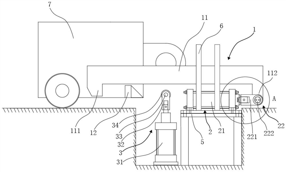
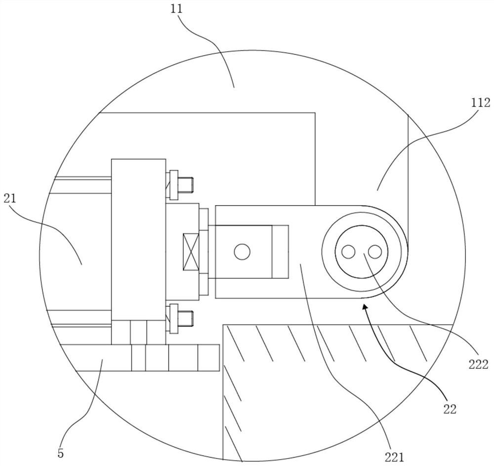
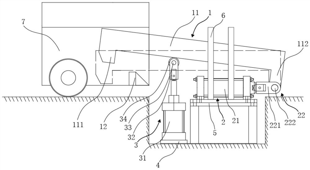
The invention discloses a locking device used for positioning a trolley and seal head stamping equipment. The locking device used for positioning the trolley comprises a locking structure, a horizontal dragging mechanism and a jacking mechanism. The locking structure comprises a pulling plate and a locking piece fixedly arranged on the trolley, a bent edge used for hooking the locking piece is formed on one side of the pulling plate, the horizontal dragging mechanism comprises a locking oil cylinder and a hinging assembly for hinging the end of a piston rod of the locking oil cylinder to the other side of the pulling plate, and the jacking mechanism is arranged below the pulling plate. Thus, when a stamping workbench replaces a die, the pulling plate only needs to be jacked to the second position from the first position through the jacking mechanism, the trolley loaded with the stamping workbench is driven to the preset position, then the pulling plate falls back to the first position from the second position through the jacking mechanism, the bent edge of the pulling plate is hooked to the locking piece, then the locking oil cylinder drags the pulling plate to move in the direction deviating from the bent edge, so that the trolley moves to a preset station, and the positioning precision is high.

Description

technical field [0001] The invention belongs to the technical field of head punching equipment, and in particular relates to a locking device for positioning a trolley and head punching equipment. Background technique [0002] In the stamping process of the head, the concentricity between the stamping upper die and the stamping lower die of the stamping equipment will have a great influence on the thickness reduction, out-of-roundness and eccentricity of the formed head. , thus affecting the stamping quality of the head. At present, the weight of the lower die workbench and the lower die base set on the lower die workbench of the stamping equipment weighs more than 100 tons. Generally, the lower die workbench needs to be loaded on a trolley, and the trolley is driven by a hydraulic motor to Move the lower die table to the predetermined station. After the hydraulic motor moves the lower die table to the predetermined position, since the trolley loaded with the lower die tab...

Claims


Application Information

Patent Timeline
Patent Type & Authority Applications(China)
IPC IPC(8): B21D37/14B21D22/02
Inventor 吴亦平杨庆高叶飞黄为齐许樱妮
Owner CHANGZHOU KUANGDA WEIDE MACHINERY
Learn More