Valve device

A valve device and valve-moving technology, applied in valve device, valve operation/release device, valve lift, etc., can solve the problems of shortened valve device life, inability to ensure output, and reduced responsiveness, so as to improve response speed and improve Responsive, quiet life effects

Inactive Publication Date: 2007-01-10
SMC CORP
View PDF3 Cites 0 Cited by
  • Summary
  • Abstract
  • Description
  • Claims
  • Application Information

AI Technical Summary

Problems solved by technology

In that way, in the electromagnetic valve device as described in the above-mentioned Patent Document 3, the attraction force acting on the movable valve of the opening and closing valve seat by the fixed iron core of the solenoid is of course between the fixed iron core and the movable valve. The stroke becomes stronger for a short time, that is, the response is improved, and the power consumption of the solenoid is also reduced. However, since the gap between the movable valve and the valve seat (output opening) is also reduced, the required output cannot be ensured as a result. The problem
On the other hand, when the stroke between the fixed iron core and the movable valve is long, the required output can be ensured, but the suction force is low and the responsiveness is lowered with the same electric power as the case of the short stroke, so in order to suppress the responsiveness reduction, more power is required
Furthermore, due to the increased attractive force, the movable valve strongly hits the magnetic adsorption surface of the fixed iron core, etc. when the movable valve is opened, so that not only a loud knocking sound is generated, but also the life of the valve unit is shortened.

Method used


Image

  • Valve device
  • Valve device
  • Valve device

Examples


Embodiment Construction

[0029] Hereinafter, the present invention will be described in more detail based on the embodiments shown in the drawings.

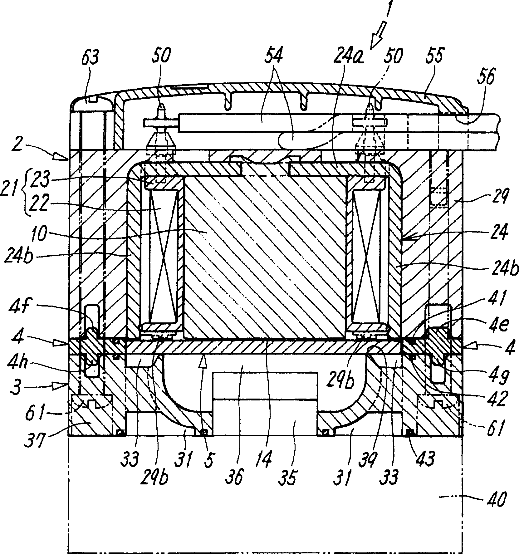
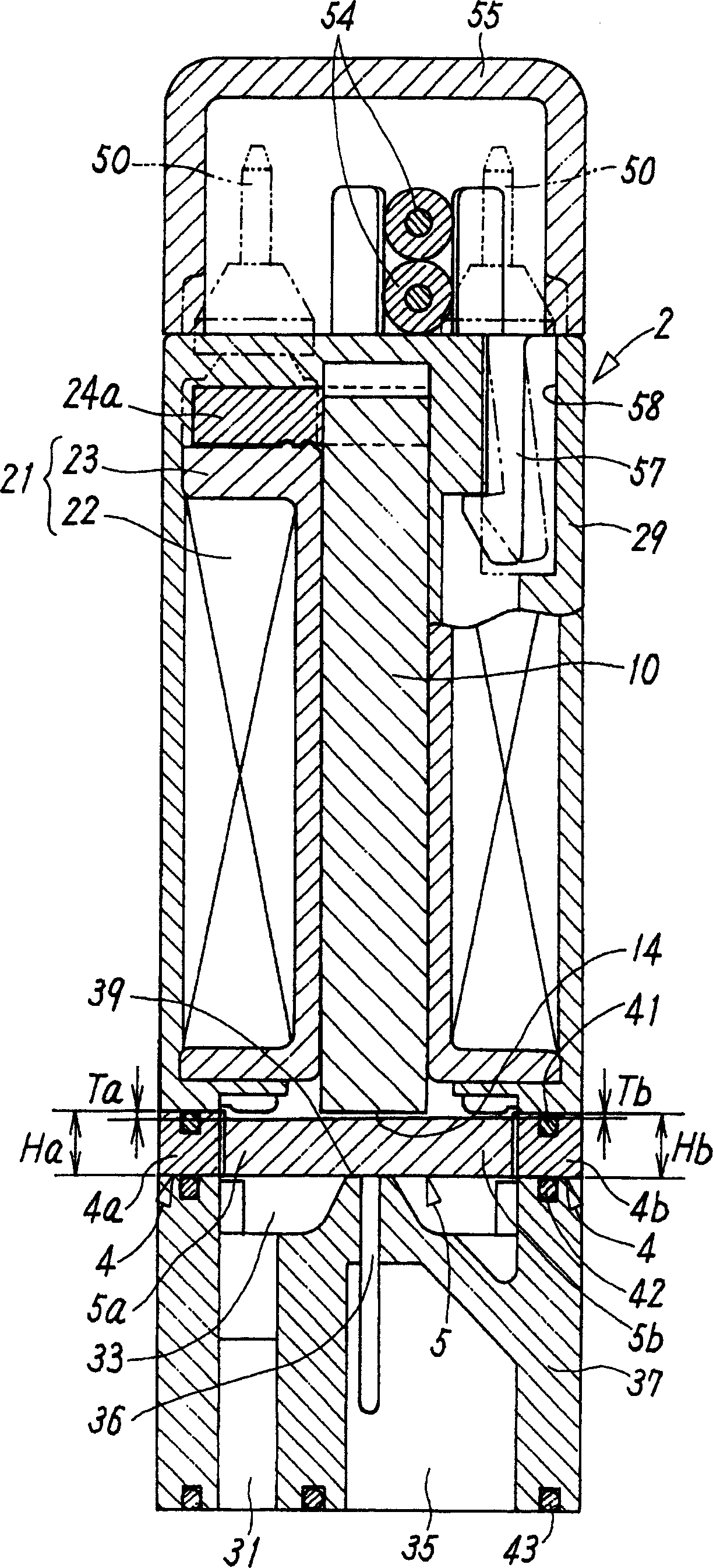
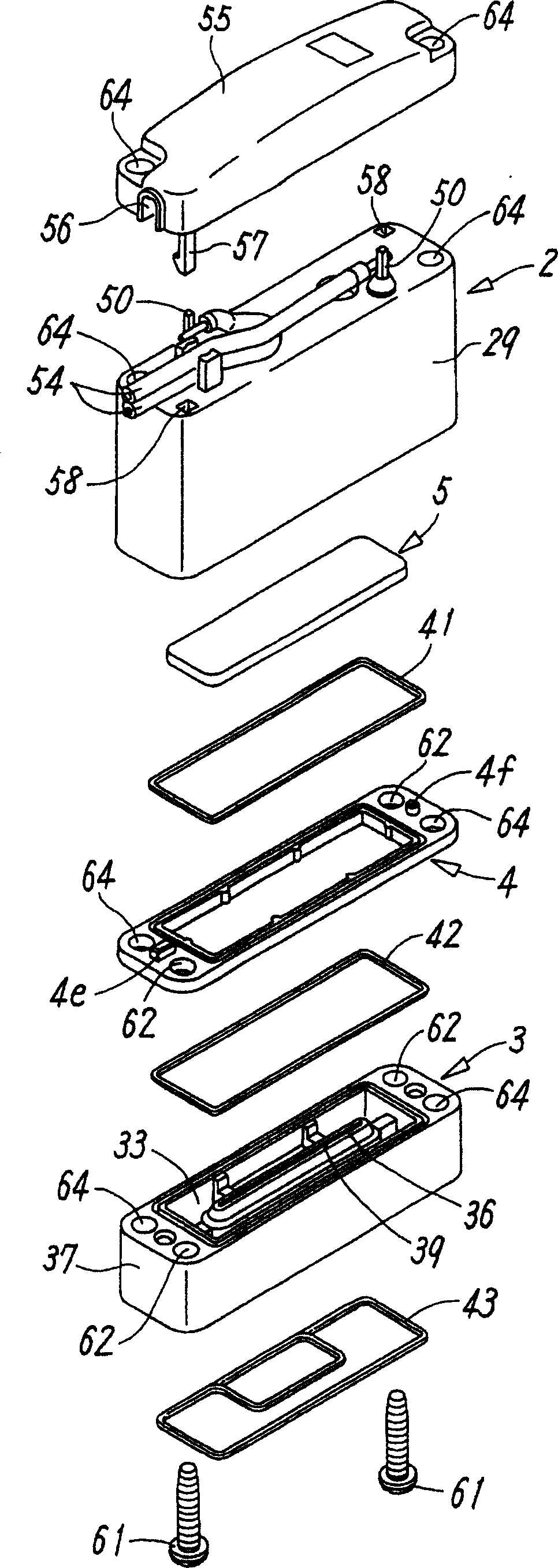
[0030] Figure 1 to Figure 4 Representing an embodiment of a valve device according to the invention, the valve device 1 has, roughly speaking, a solenoid part 2; a valve body part 3 which is connected to the solenoid part 2 and has an input of pressurized fluid Flow path 33 and output flow path 36; a plate-shaped movable valve 5 made of a paramagnetic material, which opens and closes the output flow path 36 on the valve main body portion 3 in response to the operation of the solenoid portion 2 action; and a gasket 4 which is provided between the solenoid portion 2 and the valve body portion 3 to constitute the stroke adjustment mechanism of the movable valve 5 described above.

[0031] The solenoid unit 2 has a solenoid 21 formed by winding a coil 22 on a bobbin 23, and the solenoid 21 has a fixed core 10 provided in the bobbin 23 with a substantially ...


PUM


Abstract

Provided a valve device capable of preventing impairing of response and flow rate of a movable valve, improving the response even by small electric power, and simultaneously achieving desired output though a structure of the valve device is simple. This valve device comprises a solenoid portion 2 having a magnetic adsorption face for adsorbing the movable valve 5 to one end of a fixed iron core 10 mounted in a solenoid 21, a valve body portion 3 connected with the solenoid portion, and having an input flow channel 33 and an output flow channel 36 for pressure fluid on its connecting portion, and the loose movable valve 5 made of a paramagnetic material and opening and closing a valve seat 39 around the output flow channel. Opening and closing strokes at both end portions opposite to each other, of the movable valve 5 in opening and closing the output flow channel of the valve body portion 3 by the movable valve are different from each other.

Description

technical field [0001] The present invention relates to a two-port valve device with simple structure, low power consumption and good response. Background technique [0002] Patent Document 1 discloses a technology of a valve device including: a solenoid portion having a movable iron core; and a main body portion connected to the solenoid portion and having a pressurized fluid The input flow path and the output flow path, and the valve seat between these flow paths is opened and closed by the valve body driven by the movable iron core, wherein the stroke of the movable iron core of the solenoid part can be reduced as much as possible, and thus The solenoid unit can be downsized. [0003] Furthermore, Patent Document 2 discloses a technology of an on-off valve in which the flow rate can be increased with a small stroke and the opening of the flow path on the output side is opened and closed by a plate-shaped valve body driven by electromagnetic force or the like. Miniaturiz...

Claims


Application Information

Patent Timeline
Patent Type & Authority Applications(China)
IPC IPC(8): F16K1/00F16K31/06
Inventor 芳村亲一加藤久隆
Owner SMC CORP
Why Eureka
Try Eureka