Flat type heat-pipe

A flat, heat pipe technology, applied in indirect heat exchangers, lighting and heating equipment, cooling/ventilation/heating transformation, etc., can solve problems such as dry burning of electronic products

Inactive Publication Date: 2007-01-10
FURUI PRECISE COMPONENT (KUNSHAN) CO LTD +1
View PDF0 Cites 36 Cited by
  • Summary
  • Abstract
  • Description
  • Claims
  • Application Information

AI Technical Summary

Problems solved by technology

[0005] In order to solve the heat dissipation problem of electronic products with narrow space constraints and prevent the technical problem of dry burning of heat pipes, it is necessary to provide a flat heat pipe that can promote the timely return of condensed liquid

Method used


Image

  • Flat type heat-pipe
  • Flat type heat-pipe
  • Flat type heat-pipe

Examples


Embodiment Construction

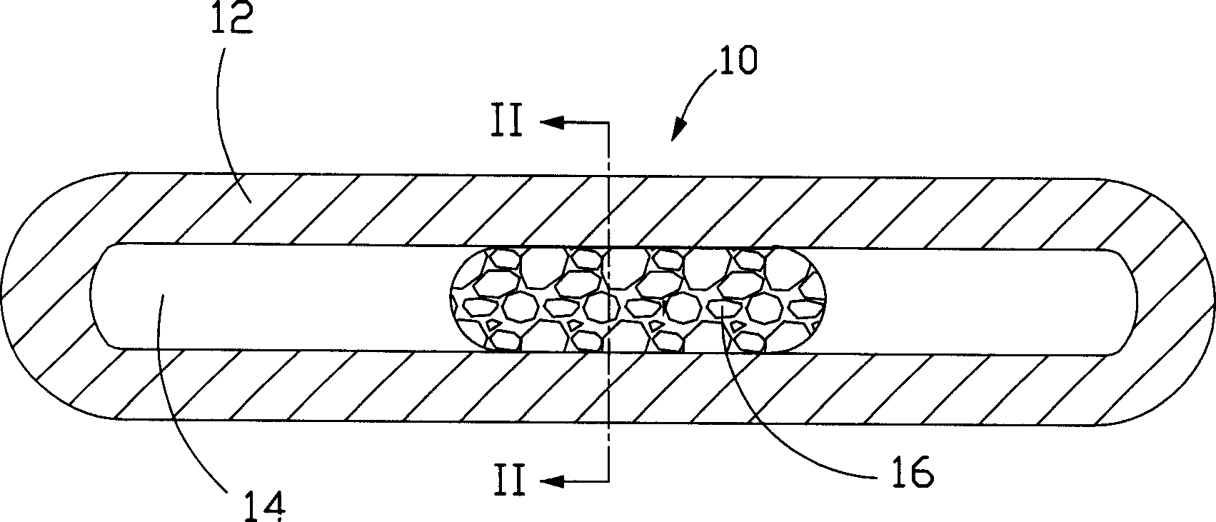
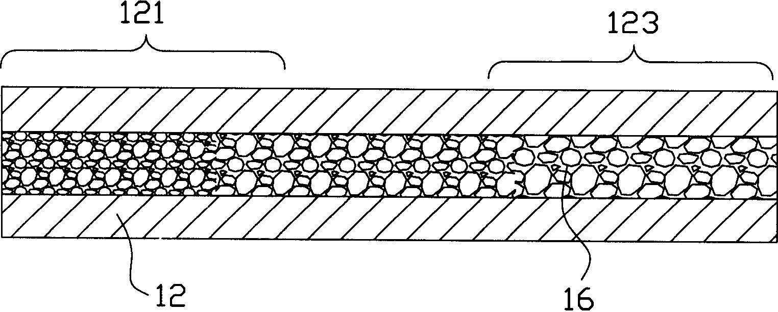
[0015] Such as Figure 1 to Figure 2 Disclosed as the first embodiment of the flat heat pipe of the present invention, the heat pipe 10 is flat and includes a casing 12, and a cavity 14 is formed in the casing 12, and the cavity 14 is filled with an appropriate amount of working liquid (not shown in the figure), the housing 12 can be made of materials with good thermal conductivity such as copper, aluminum, etc., one end forms the evaporation section 121, and the other end forms the condensation section 123, please refer to figure 2 shown. A capillary structure 16 is disposed in the center of the cavity 14 , and the spaces on the left and right sides of the cavity 14 without the capillary structure 16 form air passages for steam circulation. The capillary structure 16 is metal foam (foam metal), which is a three-dimensional space mesh porous structure sandwiched between the upper and lower inner walls of the housing 12, and extends from the condensation section 123 to the ev...


PUM


Abstract

The present invention discloses flat type heat tube. It contains one shell with inner cavity having sparkle metal constructed capillary structure, said shell including one evaporator and one condense section, said capillary structure aperture condense section sequence distributed from large to small, thereby cooled liquid in pair tube having capillary force and backflow resistance to make liquid backflow in time and effectively preventing dry cremation phenomena occurrence.

Description

【Technical field】 [0001] The invention relates to a heat transfer device, in particular to a flat heat pipe used for heat dissipation of electronic products. 【Background technique】 [0002] With the continuous development of the information industry, the electronic components are driven towards light, thin, small, high-frequency and high-speed evolution, and the heat generated by electronic components is also increasing. For electronic products with space constraints such as notebook computers, the problem of heat dissipation is more prominent, and heat pipes are widely used in these electronic products with small spaces due to their fast heat transfer speed and small footprint, and Due to the limitation of the space of these electronic products and their own characteristics, the heat pipes used are generally micro heat pipes or flat heat pipes. [0003] The heat pipe uses the principle that the temperature of the liquid remains unchanged when it changes between gas and liq...

Claims


Application Information

Patent Timeline
Patent Type & Authority Applications(China)
IPC IPC(8): F28D15/04H05K7/20
CPCF28D15/046F28D15/0233H01L23/427H01L2924/0002H01L2924/00
Inventor 孟劲功黄清白
Owner FURUI PRECISE COMPONENT (KUNSHAN) CO LTD
Why Eureka
Try Eureka