Centrifugal fan

A centrifugal fan and shaft center technology, which is applied in the direction of mechanical equipment, machine/engine, liquid fuel engine, etc., can solve the problems of large working noise, large working pressure difference of centrifugal fan, air pressure leakage, etc., so as to improve work efficiency and work quality , Increase the air volume and air pressure, and increase the effect of return resistance

Pending Publication Date: 2021-06-11
四川长虹空调有限公司
View PDF0 Cites 0 Cited by
  • Summary
  • Abstract
  • Description
  • Claims
  • Application Information

AI Technical Summary

Problems solved by technology

The working pressure difference of the centrifugal fan is relatively large, especially between the air inlet and outlet of the centrifugal fan, and due to the existence of the gap between the impeller and the volute of the centrifugal fan, the air pressure leakage problem will be serious when the centrifugal fan is working, which will not only Reduce the air volume, affect the working efficiency of the centrifugal fan, and generate a lot of working noise

Method used


Image

  • Centrifugal fan
  • Centrifugal fan
  • Centrifugal fan

Examples


Embodiment

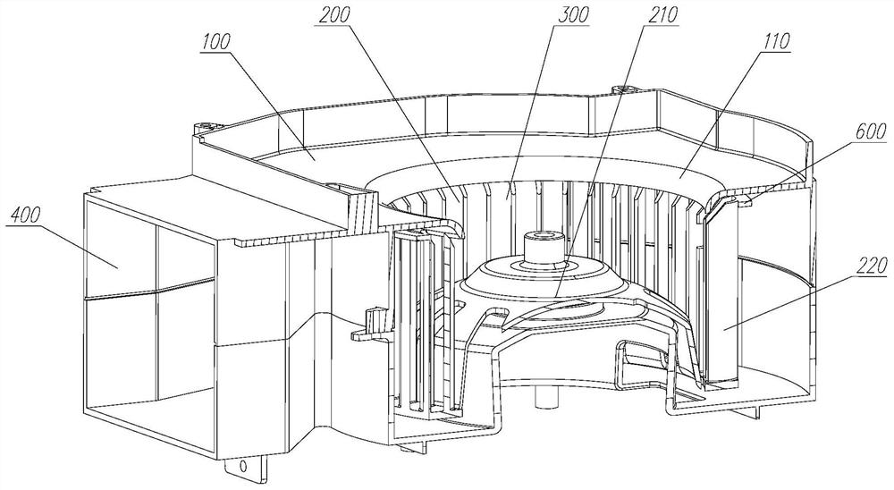
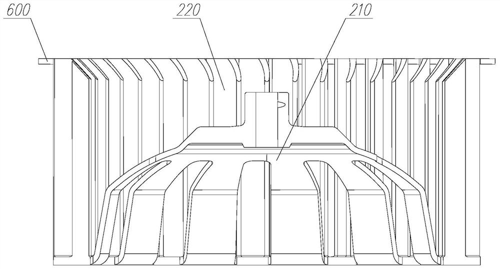
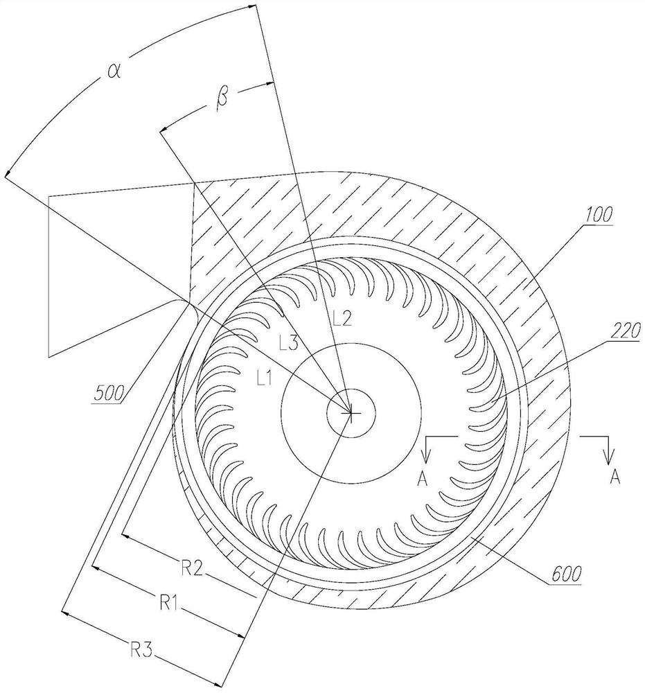
[0026]The impeller blade radius of the centrifugal fan is 75mm, the impeller height is 80mm, the number of blades is 41, and the thickness of the ring fixed head is H 1 2mm, the gap H between the axial direction of the impeller and the volute 3 The distance R between the inner wall of the volute in the area of ​​the volute tongue at the narrowest part of the flow channel of the centrifugal fan and the center of the impeller axis is 3.5mm 3 is 85mm. The radius of the annular fixing strip in the conventional centrifugal fan is 77mm, and the radius R of the annular fixing strip is set in this embodiment 1 is 82mm, and set the height H of the boss 2 is 60mm, and the inclination angle of the bevel at the end of the boss is 30°. Comparing the centrifugal fan with the conventional structure, the air volume of the centrifugal fan in this embodiment is increased by 3%, and the air output efficiency is increased by 2%.


PUM


Abstract

The invention discloses a centrifugal fan. The centrifugal fan comprises a volute and an impeller and further comprises an annular fixing strip, the annular fixing strip surrounds the impeller and is fixedly connected with the top of an outer edge of a blade, and the root of an inner edge of the blade is fixedly connected with a wheel disc; and a circle of boss surrounding the impeller is fixed to the inner wall, on the same side as an air inlet, of the volute, and a gap is reserved between the boss and the outer edge of the impeller. According to the centrifugal fan, the backflow resistance between an outlet and an inlet of the impeller is increased, and air pressure leakage at the gap between the impeller and the volute of the centrifugal fan can be effectively prevented; and under the condition that the effective working area of the impeller is guaranteed, the air outlet amount and the air outlet pressure of the centrifugal fan can be effectively improved, and the working efficiency and the working quality of the centrifugal fan are improved.

Description

technical field [0001] The invention relates to the technical field of fan equipment, in particular to a centrifugal fan. Background technique [0002] According to the principle of converting kinetic energy into potential energy, the centrifugal fan can use the high-speed rotating impeller to accelerate the gas, then decelerate and change the flow direction, so that the kinetic energy can be converted into potential energy, which can increase the gas pressure and discharge the gas. Since the impeller of the centrifugal fan has problems of jumping along the rotating shaft and shaking in the radial direction when rotating, a sufficient gap must be left between the impeller of the centrifugal fan and the inner wall of the volute to prevent the centrifugal fan from scraping between the impeller and the volute during operation. Wipe the collision problem. The working pressure difference of the centrifugal fan is relatively large, especially between the air inlet and outlet of t...

Claims


Application Information

Patent Timeline
Patent Type & Authority Applications(China)
IPC IPC(8): F04D17/16F04D25/08F04D29/42F04D29/44F04D29/28F04D29/30
CPCF04D17/16F04D25/08F04D29/283F04D29/30F04D29/4233F04D29/441
Inventor 张仁亮
Owner 四川长虹空调有限公司
Why Eureka
Try Eureka