Screw shaft assembly and double-screw conveying device thereof

A conveying device and screw shaft technology, applied in the field of double-screw conveying, can solve the problems of large conveying resistance, difficult to clean, low conveying efficiency of viscous slurry, etc., and achieve the effect of improving the accuracy of processing and assembly

Inactive Publication Date: 2021-02-26
XINGTAI HAI YU LITHIUM BATTERY EQUIP LTD
View PDF10 Cites 0 Cited by
  • Summary
  • Abstract
  • Description
  • Claims
  • Application Information

AI Technical Summary

Problems solved by technology

[0003] The transportation of existing battery slurry generally uses screw pumps to pressurize and use pipelines for long-distance transportation. However, with the development of battery materials, the transportation of more viscous positive and negative electrode slurry has been mentioned. The existing long-distance pipelines The problem of difficult cleaning and high resistance of road transportation has been exposed. The screw conveyor is an effective way to solve this problem. However, the existing screw conveyor has its own limitations and cannot be used well in practical engineering applications. effect, there are the following problems:
[0004] The gap between the tube wall and the screw blade of the screw conveyor is large, and the viscous material to be transported will accumulate in the gap. At the same time, the material accumulation will also occur on the screw and the blade. Since the battery slurry has a certa...

Method used


Image

  • Screw shaft assembly and double-screw conveying device thereof
  • Screw shaft assembly and double-screw conveying device thereof
  • Screw shaft assembly and double-screw conveying device thereof

Examples


Embodiment 1

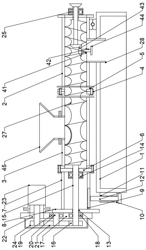
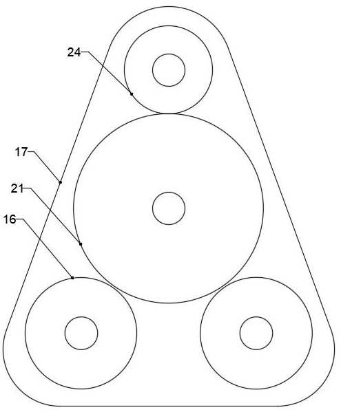
[0027] Embodiment one, such as Figure 1-6 As shown, a double-screw conveying device includes a rectangular base 1, and one end of the upper surface of the rectangular base 1 is provided with a self-cleaning mechanism;

[0028] The self-cleaning mechanism includes a shell one 2 on one end of the upper surface of the rectangular base 1, one end of the shell one 2 is hinged to the rectangular base 1, one end of the shell one 2 is installed with a shell two 3, and the two ends of the shell one 2 and the two ends of the shell two 3 are respectively equipped with flange pieces 4. Fastening bolts 5 are installed on the outer ring of the flange piece 4, a flange ring 6 is installed on one end of the shell 23, and a fixing rod 7 is installed on the side surface of the flange ring 6. There are four fixing rods 7, and one end of the fixing rod 7 A connecting plate 8 is installed, a support plate 9 is installed at the lower end of the fixed rod 7, a fixed block 10 is installed at one end...

Embodiment 2

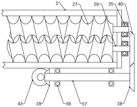
[0036] Embodiment two, such as Figure 1-5 and Figure 7 , Figure 8 As shown, a double-screw conveying device includes a rectangular base 1, and one end of the upper surface of the rectangular base 1 is provided with a self-cleaning mechanism;

[0037] The self-cleaning mechanism includes a shell one 2 on one end of the upper surface of the rectangular base 1, one end of the shell one 2 is hinged to the rectangular base 1, one end of the shell one 2 is installed with a shell two 3, and the two ends of the shell one 2 and the two ends of the shell two 3 are respectively equipped with flange pieces 4. Fastening bolts 5 are installed on the outer ring of the flange piece 4, a flange ring 6 is installed on one end of the shell 23, and a fixing rod 7 is installed on the side surface of the flange ring 6. There are four fixing rods 7, and one end of the fixing rod 7 A connecting plate 8 is installed, a support plate 9 is installed at the lower end of the fixed rod 7, a fixed bloc...


PUM


Abstract

The invention discloses a screw shaft assembly and a double-screw conveying device thereof. The screw shaft assembly comprises a rectangular base, a self-cleaning mechanism is arranged at one end of the upper surface of the rectangular base, and an output anti-blocking mechanism is arranged at the other end of the upper surface of the rectangular base. The screw shaft assembly and the double-screwconveying device thereof have the beneficial effects that double screws are engaged with each other and rotate in the same direction through conjugate threads, meanwhile, the part machining and assembling precision is improved, the assembling gaps between the screws and between the screws and the inner wall of a barrel are reduced, and the purposes of self-cleaning between the screws, self-cleaning between the screws and the wall of the barrel and material stirring and mixing are achieved. The slurry backflow gap of a single screw is blocked through conjugate meshing of the threads between the screws, the backflow resistance of the slurry is effectively increased, and the purposes of preventing materials from being blocked and flowing back easily, improving the slurry conveying efficiencyand establishing relatively stable outlet pressure are achieved.

Description

technical field [0001] The invention relates to the technical field of double-screw conveying, more specifically, to a screw shaft assembly and a double-screw conveying device. Background technique [0002] At present, the existing similar conveying equipment on the market is the traditional single and double screw conveyor. The screw conveyor is composed of three parts: the conveyor body, the inlet and outlet, and the driving device. The screw machine body is composed of head bearings, tail bearings, suspension bearings, It is composed of screw, casing, cover plate and base. The driving device is composed of a motor, a reducer, a coupling and a base; [0003] The transportation of existing battery slurry generally uses screw pumps to pressurize and use pipelines for long-distance transportation. However, with the development of battery materials, the transportation of more viscous positive and negative electrode slurry has been mentioned. The existing long-distance pipelin...

Claims


Application Information

Patent Timeline
IPC IPC(8): B65G33/26B65G33/14B65G33/24
CPCB65G33/14B65G33/24B65G33/265
Inventor 王俊勇王俊涛张继超胡跃辉
Owner XINGTAI HAI YU LITHIUM BATTERY EQUIP LTD
Why Eureka
Try Eureka