Composite liquid sucking core of toothed heat pipe and manufacturing method thereof

A manufacturing method and a liquid absorbing core technology are applied in the field of heat pipes for heat transfer, which can solve the problems of low backflow resistance, low thermal resistance, and large capillary pressure, and achieve the effects of reducing backflow resistance, enhancing evaporation and condensation, and improving capillary force.

Active Publication Date: 2013-04-10
SOUTH CHINA UNIV OF TECH
View PDF4 Cites 0 Cited by
  • Summary
  • Abstract
  • Description
  • Claims
  • Application Information

AI Technical Summary

Problems solved by technology

[0004] The purpose of the present invention is to overcome the deficiencies of the existing heat pipe liquid-absorbent core, and propose a toothed heat pipe composite liquid-absorbent core with high capillary pressure, small return resistance and low thermal resistance

Method used


Image

  • Composite liquid sucking core of toothed heat pipe and manufacturing method thereof
  • Composite liquid sucking core of toothed heat pipe and manufacturing method thereof
  • Composite liquid sucking core of toothed heat pipe and manufacturing method thereof

Examples


Embodiment 1

[0038] A method for manufacturing a composite liquid-absorbing core of a toothed heat pipe, comprising the following steps and process conditions:

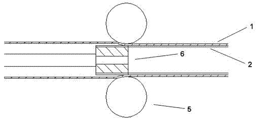
[0039] (1) Processing of toothed heat pipes: Using the high-pressure oil layer in the closed cavity, the spinning ball is used to spin the outer wall of the copper tube to transfer the spinning pressure. Under the action of extrusion force, plastic deformation occurs locally, and micro grooves are processed.

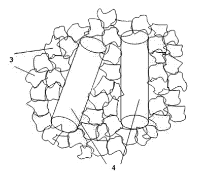
[0040] (2) Filler: Use copper powder particles with a particle size of 100-140 mesh. The copper powder particles are spherical copper powder and irregular copper powder, with irregular copper powder particles being the majority. Take copper fibers with a diameter of 150 μm and a length of 2 mm, and the mass ratio of copper powder particles to copper fibers is 8:1; put a mandrel in a copper round tube to form a ring-shaped liquid-absorbing core to fill the space, and fill in a certain quality of copper powder A mixture of pa...

Embodiment 2

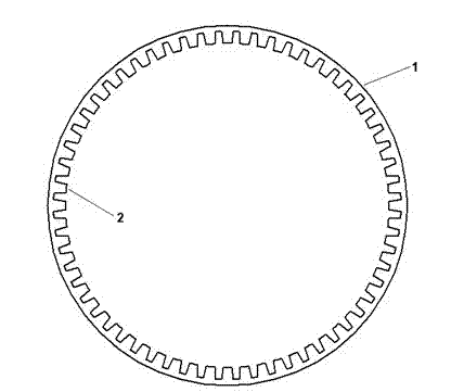
[0046] Compared with Example 1, the difference is that the number of groove teeth on the wall of the copper circular tube is 55, the tooth height is 0.25mm, and the tooth width is 0.17mm. The particle size of the copper powder is 120 mesh to 140 mesh, and the single length of the copper fiber is 2mm. The mass of the two is mixed at a ratio of 10:1 to form a sintered material. The heat preservation and sintering temperature is 940° C., and the heat preservation is 90 minutes to obtain a composite liquid-absorbing core. The heat transfer effect is basically the same as in Example 1.

Embodiment 3

[0048] Compared with Example 1, the difference is that the number of groove teeth on the wall of the copper circular tube is 60, the tooth height is 0.25mm, and the tooth width is 0.15mm. The particle size of the copper powder is 80 mesh to 100 mesh, and the single length of the copper fiber is 2mm. The mass of the two is mixed at a ratio of 6:1 to form a sintered material. The heat preservation and sintering temperature is 970° C., and the heat preservation is 90 minutes to obtain a composite liquid-absorbing core. The heat transfer effect is basically the same as in Example 1.


PUM

PropertyMeasurementUnit
lengthaaaaaaaaaa
diameteraaaaaaaaaa
particle diameteraaaaaaaaaa

Abstract

The invention discloses a composite liquid sucking core of a toothed heat pipe and a manufacturing method thereof. Red copper powder particles and red copper fibers of the composite liquid sucking core are mixed and sintered on micro-grooves of the inner wall of a red copper pipe; two pore structures are formed among the red copper powder particles and between the red copper powder particles and the red copper fibers as well as between the red copper powder particles and the micro-grooves of the pipe wall; the copper powder has the particle size of 80 meshes to 200 meshes; and the red copper fibers have the length of 2mm-10mm. During manufacturing, the micro-grooves of the pipe wall are machined on a bare red copper pipe in a rotary pressing manner; a core rod is inserted into a groove copper pipe to form the space range of the liquid sucking core, and a mixture of the copper powder particles and the red copper fibers is uniformly filled in the space; the groove copper pipe is placed in a vacuum protective type sintering furnace to be sintered; and after the furnace is cooled to room temperature, the core rod is dismantled to obtain the composite liquid sucking core. The inventionhas the characteristics of simple manufacturing process, low production cost as well the heat pipe and the groove heat pipe sintering and provides the composite liquid sucking core of the toothed heat pipe, which has large capillary pressure, low thermal resistance and strong mechanical strength.

Description

technical field [0001] The invention relates to a heat pipe for heat transfer, in particular to a composite liquid-absorbing core structure of a toothed heat pipe and a manufacturing method thereof. Background technique [0002] With the rapid development of today's microelectronics technology, the surface area of ​​chips is gradually shrinking, and the heat flux is increasing sharply, resulting in poor heat dissipation of microelectronics products and greatly reducing the service life of components. The traditional heat dissipation structure has been difficult to meet the needs of the microelectronics industry at this stage. The heat pipe with the characteristics of high thermal conductivity, high reliability, fast thermal response, and no need for additional electric drive has therefore become an ideal condition for cooling chips with high heat flux density. The heat transfer performance of the heat pipe is mainly determined by the structure of the capillary wick. At prese...

Claims


Application Information

Patent Timeline
Patent Type & Authority Patents(China)
IPC IPC(8): F28D15/04B22F7/08
Inventor 李勇陈镇宇陈举聪何成彬欧元贤曾志新
Owner SOUTH CHINA UNIV OF TECH
Why Eureka
Try Eureka