Communication path redundancy protection systems and methods

A technology of communication path and communication system, applied in the field of redundancy protection

Inactive Publication Date: 2007-01-10
ALCATEL LUCENT SAS
View PDF0 Cites 27 Cited by
  • Summary
  • Abstract
  • Description
  • Claims
  • Application Information

AI Technical Summary

Problems solved by technology

[0005] Therefore, although VRRP provides a level of protection against gateway router failures, there are still significant challenges in how to provide highly available IP services

Method used


Image

  • Communication path redundancy protection systems and methods
  • Communication path redundancy protection systems and methods
  • Communication path redundancy protection systems and methods

Examples


Embodiment Construction

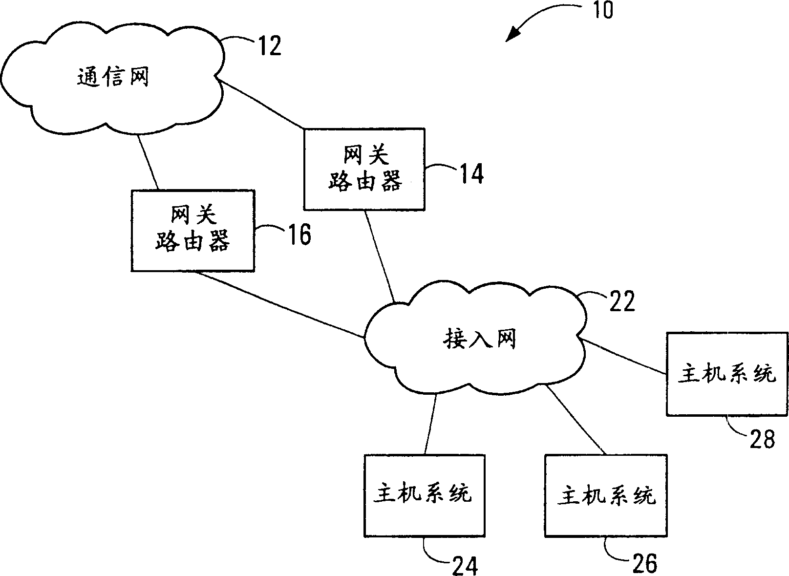
[0031] figure 1 is a block diagram of a communication system implementing redundant gateway routers. The communication system 10 includes a communication network 12 , redundant gateway routers 14 , 16 , an access network 22 and host systems 24 , 26 , 28 . In a typical VRRP installation, the communication network 12 is an IP network, the gateway routers 14, 16 are IP routers, the access network 22 is a LAN, and the host systems 24, 26, 28 are IP hosts. Those skilled in the art should be familiar with figure 1 components shown and are therefore only briefly described here.

[0032] Dynamic IP routing is already the criterion for generating network deployments in so-called core networks, eg the communication network 12 . However, the access network 22 connected to the host systems 24, 26, 28 typically retains a static and default routing environment.

[0033] This scenario is common in service provider networks. In a service provider network, the host systems 24, 26, 28 may ...


PUM


Abstract

Communication path redundancy protection systems and methods are disclosed. Multiple communication interfaces having a common address support communications on respective communication paths. One of the interfaces or communication paths is selected as an active interface or path for transferring communication traffic. In the event of a fault associated with the active interface or path, another one of the interfaces or paths is selected to become active. The common address allows redundant interfaces to appear as a single interface to other communication equipment, whereas the multiple interfaces provide redundant path protection using a single piece of communication equipment. When embodiments of the invention are implemented in a gateway router of a core communication network, for example, activity switches between redundant access paths have no effect on routing in the core network.

Description

technical field [0001] The present invention relates generally to communications, and more particularly to providing redundant protection for communications paths in a communications system. Background technique [0002] Securing communication systems to provide reliable service and high availability is an ongoing challenge for operators and service providers. Equipment redundancy is an example of a common protection scheme. In an equipment redundancy protection system, groups of components are deployed which are able to perform the same function or at least a common protection function. Only one redundant component in a redundant set is usually dependent on performing the protection function at any one time, and is often referred to as the "active" component. The other components of the redundancy group (one or more "standby" components) are typically idle until a failure of the active component is detected. In this event, activity is switched from the failed active comp...

Claims


Application Information

Patent Timeline
Patent Type & Authority Applications(China)
IPC IPC(8): H04L1/22H04L29/10
CPCH04L12/2854H04L12/46H04L45/28H04L45/00H04L45/22
Inventor M·布罗瑟斯顿H·昌
Owner ALCATEL LUCENT SAS
Why Eureka
Try Eureka