

Variable valve system
A valve mechanism and variable technology, applied in mechanical equipment, combustion engines, engine control, etc., can solve problems such as changes in valve body action angle and lift, and achieve the effect of avoiding the influence of temperature changes
- Summary
- Abstract
- Description
- Claims
- Application Information
AI Technical Summary
Problems solved by technology
Method used
Image

Examples
no. 1 example
[0049] [Overall structure of variable valve train]
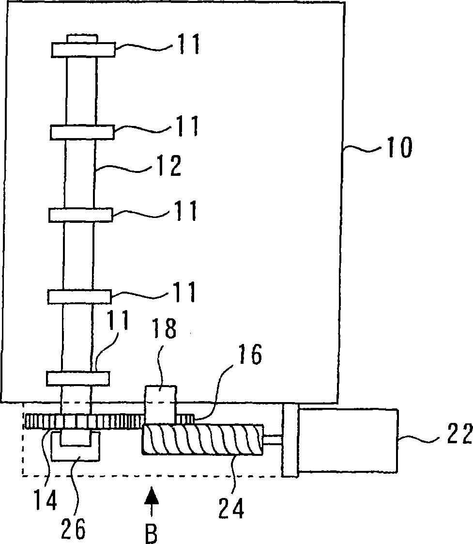
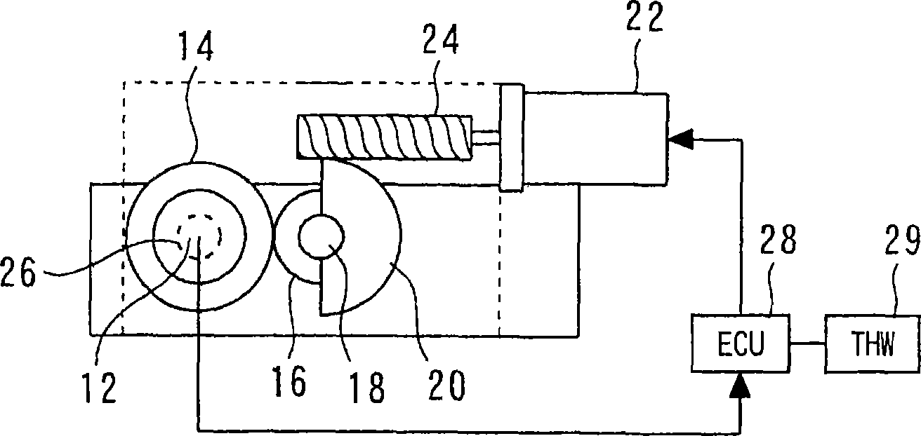
[0050] Figure 1A with 1B shows the overall structure of the variable valve train according to the first embodiment of the present invention; more specifically, Figure 1A is a plan view representing the entire variable valve train, and Figure 1B is from Figure 1A The side view when viewed from the B direction.
[0051] Figure 1A with 1B The illustrated structure includes a cylinder head 10 of an internal combustion engine. The cylinder head 10 has a plurality of control shaft bearings 11 located on both sides of each cylinder. The control shaft bearing 11 holds the control shaft 12 so that the control shaft 12 can rotate. The internal combustion engine of the present embodiment has four cylinders arranged in series. The control shaft 12 is arranged longitudinally across the four cylinders.
[0052] Each cylinder of the internal combustion engine has an intake valve and an exhaust valve, which are opened / closed sync...
no. 2 example
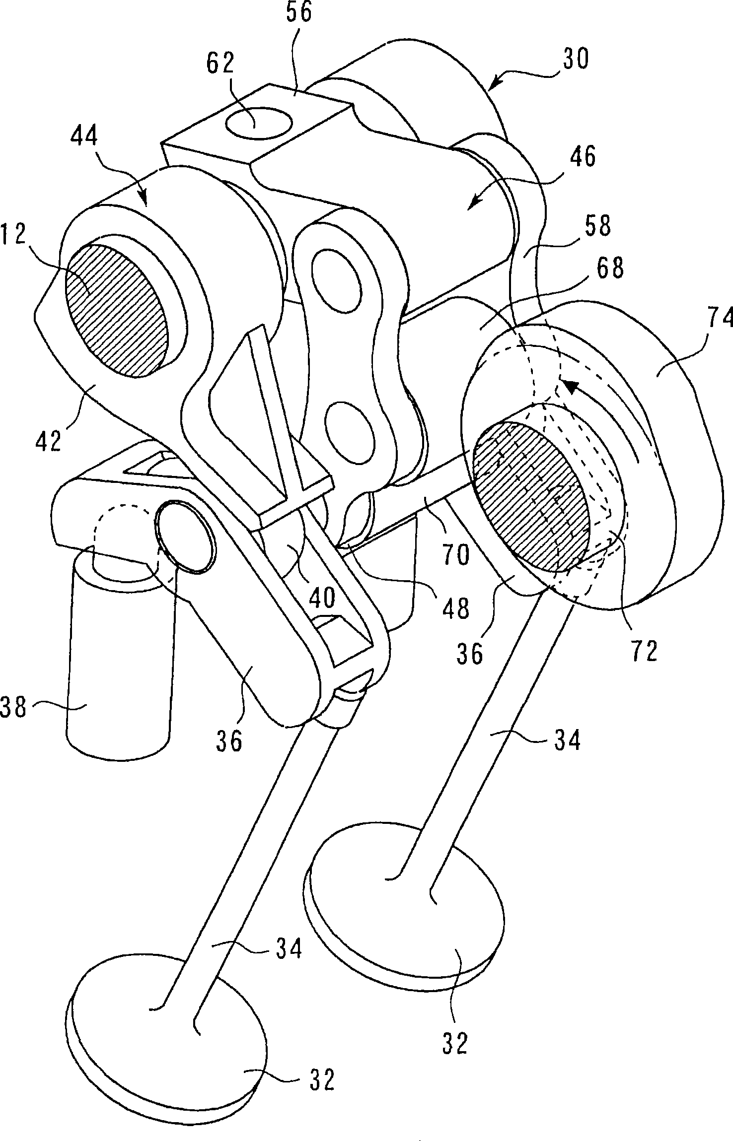
[0111] refer to Figures 1A to 5B A second embodiment of the present invention is described. The variable valve mechanism of the second embodiment has the same structure as that of the first embodiment. As far as the mechanism of the first embodiment is concerned, the components used to determine the distance between the control shaft 12 and the camshaft 72, that is Figure 4A The distance L shown, and the components arranged between the control shaft 12 and the camshaft 72 are made of materials with different linear expansion rates, and the angle of action can be corrected according to the ambient temperature of the cylinder head 10 to avoid thermal expansion and The effect of shrinkage.
[0112] However, in the case of the variable valve mechanism of the second embodiment, the part for determining the distance L (that is, the cylinder head 10), and the part between the control shaft 12 and the camshaft 72 (that is, the first arm part) 44 and the second arm member 46) are ...
no. 3 example
[0116] A third embodiment of the present invention is described with reference to FIGS. 8 to 10 . The variable valve mechanism of the third embodiment has the same structure as that of the first embodiment.
[0117] [Problems of the variable valve mechanism according to the present embodiment]
[0118] In order to properly operate the internal combustion engine, it is necessary to properly set the operating angle and the lift amount according to the operating state of the internal combustion engine. More specifically, when the internal combustion engine is started, it is necessary to set the operating angle and lift amount to be suitable for starting. However, when the internal combustion engine is stopped, the operating angle and the lift amount are not always set to a state suitable for starting the internal combustion engine. Therefore, for an internal combustion engine equipped with a variable valve train, it is necessary to correct the operating angle and lift amount wi...
PUM
 Abstract
Description
Claims
Application Information