
Paper separating mechanism and paper separation and focusing mechanism using same

A technology of separation mechanism and aggregation mechanism, which is applied in the direction of pile separation, object separation, thin material processing, etc., and can solve problems such as posture deviation

Inactive Publication Date: 2007-01-17
OKI ELECTRIC IND CO LTD
View PDF1 Cites 5 Cited by
  • Summary
  • Abstract
  • Description
  • Claims
  • Application Information

AI Technical Summary

Problems solved by technology

[0004] However, in the prior art described above, when the papers are sent out, the papers are pushed by the pick-up rollers, so there is a large friction between the collected papers at the parts pushed by the pick-up rollers. The balance between the friction between the paper and the second paper and the friction between the second paper and the third paper may be caused by the influence of the first paper on the second paper Movement, its posture deviates, especially when one side of the second sheet moves in the sending direction and the other side does not move, the posture of the sheet becomes greatly deviated, and when such a sheet is sent out, It may cause troubles such as paper jams in the paper conveying path

Method used


Image

  • Paper separating mechanism and paper separation and focusing mechanism using same
  • Paper separating mechanism and paper separation and focusing mechanism using same
  • Paper separating mechanism and paper separation and focusing mechanism using same

Examples


Embodiment 1

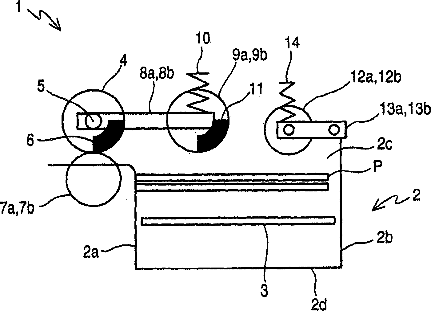
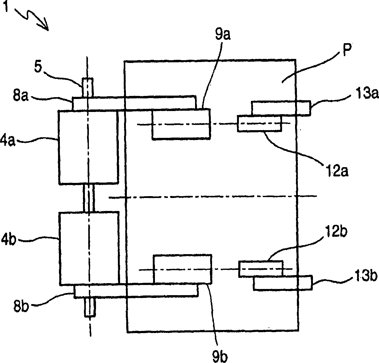
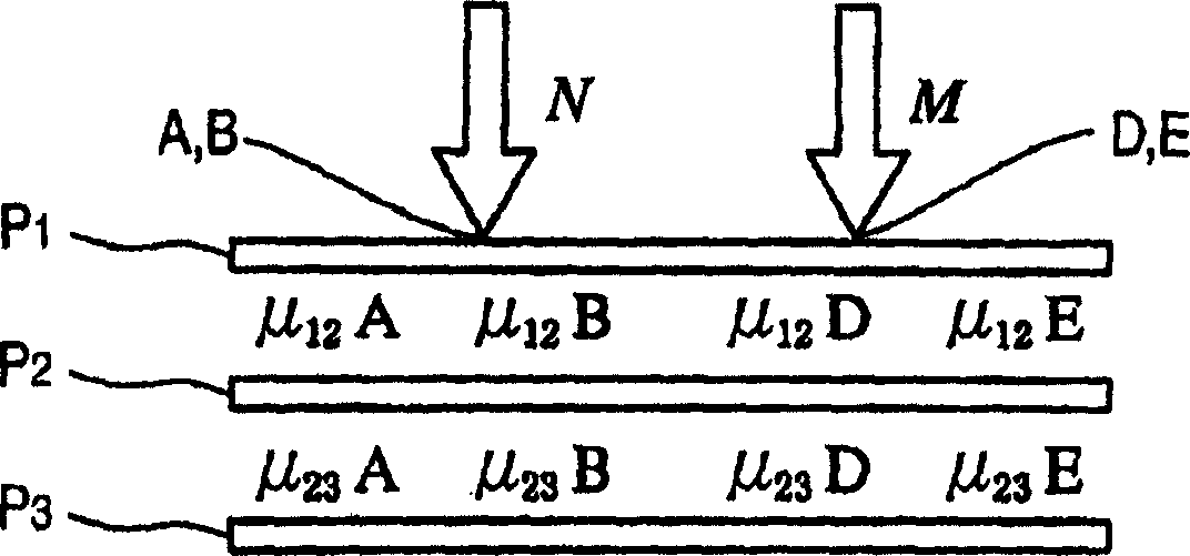
[0039] figure 1 To show a side view of the sheet separation mechanism of Embodiment 1, figure 2 In order to show the top view of the sheet separation mechanism of Embodiment 1, image 3 It is an explanatory diagram showing the force acting on the gathered sheets of Example 1, Figure 4 It is an explanatory diagram showing the force acting on the next sheet of paper when the sheet of Example 1 is fed out.

[0040] exist figure 1 , figure 2 Among them, symbol 1 is the paper separation mechanism.

[0041] Reference numeral 2 is a paper storage section, which is a box body including a front panel 2a, a rear panel 2b provided opposite to the front panel 2a, and a pair of side panels 2c and a bottom panel 2d provided on the sides of the front panel 2a and the rear panel 2b. , has a table 3 that is reciprocally moved away from or close to the bottom plate 2d by a drive mechanism not shown in the figure, and the sheets P are collected on the table 3 .

[0042] figure 1 The st...

Embodiment 2

[0082] Figure 6 In order to show the top view of the sheet separation and gathering mechanism of Embodiment 2, Figure 7 It is a side view showing the sheet separation and gathering mechanism of the second embodiment.

[0083] The same reference numerals are assigned to the same parts as those in the above-mentioned first embodiment, and description thereof will be omitted.

[0084] exist Figure 6 , Figure 7 Among them, symbol 15 is a paper separation and gathering mechanism.

[0085] Reference numeral 20 denotes a paper pressing portion, which is formed by attaching one end of pressing roller arms 13a, 13b to a shaft 21 capable of reciprocating movement in the same direction as table 3 by a drive mechanism not shown in the figure.

[0086] In this example, if Figure 6 As shown, pickup arms 8a and 8b are provided on both sides of the supply roller 4a, and a pickup arm 8c with a pickup roller 9c and a pickup arm 8d with a pickup roller 9d are newly installed on both si...


PUM


Abstract

To provide a means for preventing generation of trouble such as a paper jam due to collapse of attitude of paper sheet as a moment is added to the paper sheet fed second. This paper sheet separating mechanism is provided with a stage composed to be capable of reciprocating, on which paper sheets are loaded, and picker rollers disposed on both sides of a center line along the paper sheet feeding direction to feed the paper sheets. It is provided with a pushing means to push the paper sheets loaded on the stage in the feeding upstream side more than the picker roller.

Description

technical field [0001] The present invention relates to a paper separation mechanism and a paper separation and accumulation mechanism for separating papers from a paper storage section where papers such as banknotes and receipts are collected. Background technique [0002] In the prior art sheet separation mechanism, when the sheets are fed out, the stage moves upwards, thereby pushing the accumulated sheets to the pick-up roller, and at the same time, the pick-up roller is rotated to separate the sheets one by one and send them out to the Between the supply roller and the separation roller (for example, refer to Patent Document 1). [0003] [Patent Document 1] Japanese Patent Application Laid-Open No. 05-147749 (paragraph 0019-paragraph 0020 on page 4, figure 1 ) [0004] However, in the prior art described above, when the papers are sent out, the papers are pushed by the pick-up rollers, so there is a large friction between the collected papers at the parts pushed by th...

Claims


Application Information

Patent Timeline
Patent Type & Authority Applications(China)
IPC IPC(8): B65H1/08B65H3/06
CPCB65H3/54B65H2301/4234B65H2701/1912
Inventor 大原慎司
Owner OKI ELECTRIC IND CO LTD
Learn More