Roller position adjusting device

An adjustment device and roller technology, which is applied in the field of transmission, can solve the problems that the roller shaft is not easy to move forward and backward, affect the normal operation of the transmission, and it is difficult to adjust the tension, so as to achieve stable clamping effect, prevent the roller from moving sideways, and improve the effect of friction

Inactive Publication Date: 2015-12-23
ANQING XINGFENG IND & TRADE
View PDF9 Cites 2 Cited by
  • Summary
  • Abstract
  • Description
  • Claims
  • Application Information

AI Technical Summary

Problems solved by technology

Due to the influence of mechanical vibration, the traditional rollers are prone to lateral movement during long-term working conditions, which seriously affects the normal operation of the transmission
In addition, the roller axis o

Method used


Image

  • Roller position adjusting device
  • Roller position adjusting device

Examples


Example Embodiment

[0014] The present invention will be described in detail below with reference to the accompanying drawings.

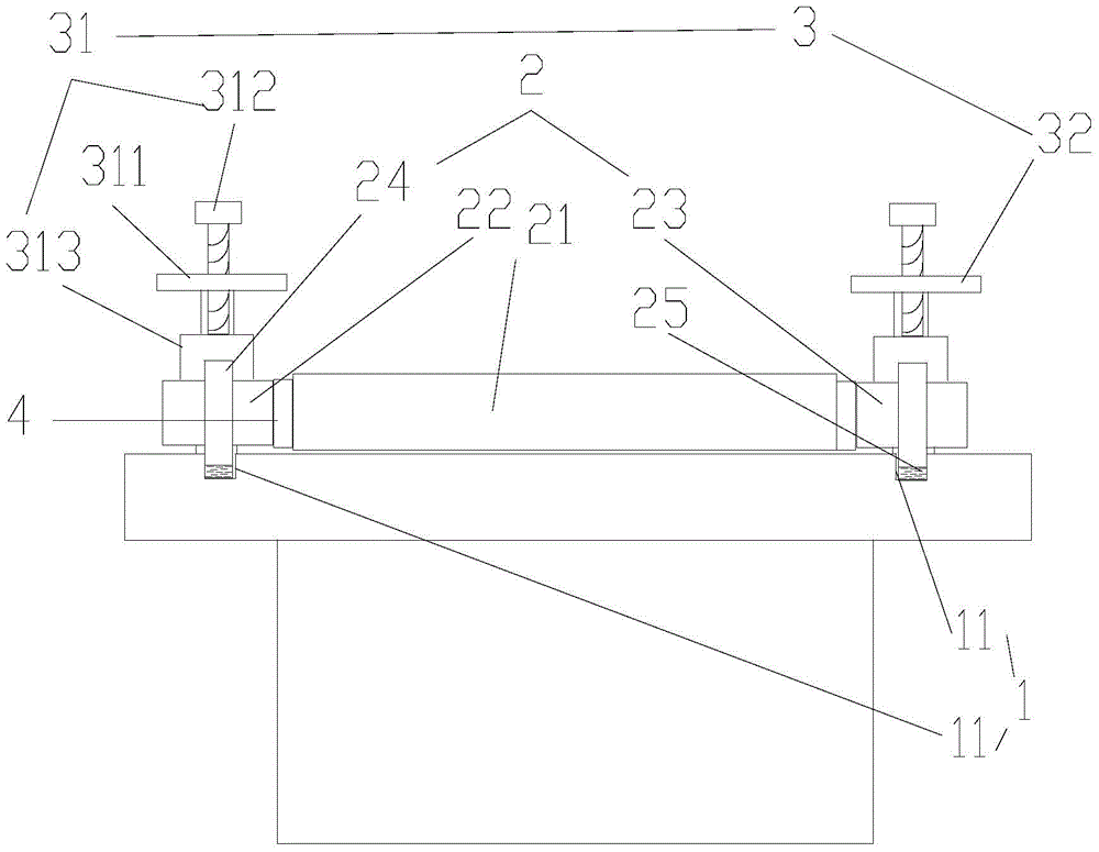
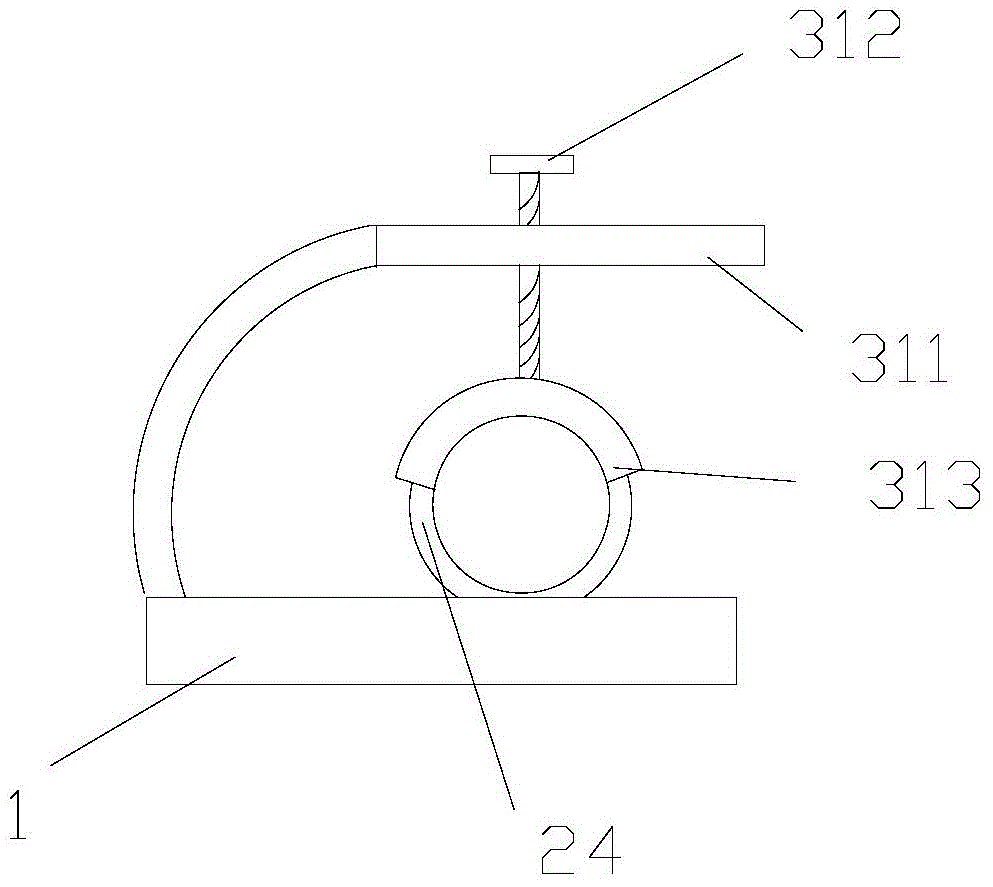
[0015] Such as Figure 1-2 As shown, the present embodiment discloses a roller position adjusting device, which includes a roller frame 1, a roller 2, and a clamping assembly 3.

[0016] The roller 2 includes a roller body 21, a left roller shaft 22, and a right roller shaft 23. The left and right ends of the roller body 1 are respectively used for mounting ends of the left roller shaft 22 and the right roller shaft 23 through a bearing 4 The connecting ends of the left roller shaft 22 and the right roller shaft 23 are respectively connected to the left and right ends of the roller frame 1 by sliding connection; the clamping assembly 3 is used to define the left roller shaft 22 , The position of the right roller shaft 23 on the roller frame 1.

[0017] The tops of the left and right ends of the roller frame 1 are provided with strip grooves 11, and the left roller shaft 22 ...


PUM


Abstract

The invention discloses a roller position adjusting device. The roller position adjusting device comprises a roller rack, a roller and a clamping assembly, wherein the roller comprises a roller body, a left roller shaft and a right roller shaft; the left end and the right end of the roller body are respectively rotationally connected with mounting ends of the left roller shaft and the right roller shaft through bearings; connection ends of the left roller shaft and the right roller shaft are respectively connected with the left end and the right end of the roller rack in a sliding manner; the clamping component is used for limiting the positions of the left roller shaft and the right roller shaft on the roller rack. The roller position adjusting device is capable of effectively preventing the roller from moving laterally and adjusting the tension by regulating the front position and the rear position.

Description

technical field [0001] The invention relates to the technical field of transmission, in particular to a roller position adjusting device. Background technique [0002] The transmission of film and cloth is often realized by the rotation of rollers. Under the long-term working condition, the traditional rollers are prone to sideways movement due to the influence of mechanical vibration, which seriously affects the normal operation of the transmission. In addition, the roller shafts of the rollers arranged on the roller frame are not easy to move forward and backward. When the tension of the film and cloth fluctuates greatly, it is difficult to adjust the tension by adjusting the front and rear positions of the rollers. Contents of the invention [0003] The invention aims at the deficiencies of the prior art and provides a roller position adjusting device which effectively prevents the rollers from moving sideways and can adjust the tension by moving the front and rear pos...

Claims


Application Information

Patent Timeline
IPC IPC(8): B65H20/02
CPCB65H20/02B65H2404/17
Inventor 朱振锋冯友宏汪建胜
Owner ANQING XINGFENG IND & TRADE
Why Eureka
Try Eureka