Check patentability & draft patents in minutes with Patsnap Eureka AI!

Electric machine, actuator with an electric machine of this type as well as use of an electric machine of this type in a motor vehicle

A technology of bearings and rotor shafts, applied in the field of servo drive mechanisms, can solve problems such as incomplete compensation of tolerances

Inactive Publication Date: 2007-01-17
SIEMENS AG
View PDF1 Cites 0 Cited by
  • Summary
  • Abstract
  • Description
  • Claims
  • Application Information

AI Technical Summary

Problems solved by technology

Due to processing and assembly technology reasons, however, tolerances cannot be fully compensated by means of such compensating elements

Method used


Image

  • Electric machine, actuator with an electric machine of this type as well as use of an electric machine of this type in a motor vehicle
  • Electric machine, actuator with an electric machine of this type as well as use of an electric machine of this type in a motor vehicle
  • Electric machine, actuator with an electric machine of this type as well as use of an electric machine of this type in a motor vehicle

Examples


Embodiment Construction

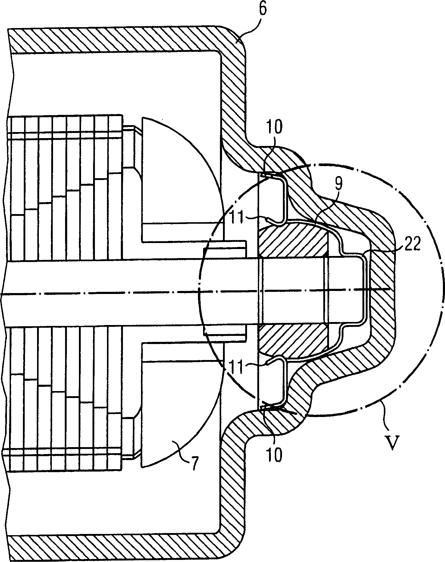
[0029] figure 1 A sectional view of an exemplary actuating drive 1 with a transmission unit 2 and an electric motor 4 according to the invention is shown. The transmission unit 2 has a transmission housing in which a worm wheel and a worm 3 meshing with the worm wheel are accommodated. The motor 4 includes a casing 6, a stator 17 and a rotor 7 for motorized drive housed in the stator. The worm 3 is located at the free end of a rotor shaft 5 driven by the electric motor 4 and partly housed in a housing 6 of the electric motor 4 . The rotor shaft 5 is guided in a bearing 8 which accommodates the motor-side end of the rotor shaft 5 and in a further bearing opposite the transmission unit 2 . exist figure 1 In the embodiment of the rotor shaft 5 is integrally formed. A two-part embodiment of the rotor shaft 5 is likewise conceivable, ie a motor shaft and a transmission shaft with a connecting element in between.

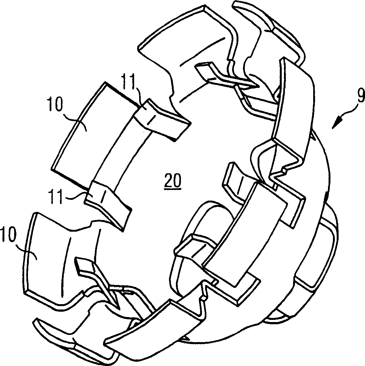
[0030] figure 2 is according to figure 1 An enlarged view of...


PUM


Abstract

The electric machine has a stator, a rotor with a rotor shaft and a bearing. One end of the rotor shaft is guided in the bearing which is inserted into a clamping nut in the axial direction. The clamping nut is fixed into a housing together with the bearing. The clamping nut forms a pot bearing, which axially limits the end of the rotor shaft guided by the bearing. The pot bearing is an axially tapered cylindrical appendage of the clamping nut which forms a springing element acting essentially axially for a possible axial movement of the pot bearing. The clamping nut effects the attachment of the engine-side bearing in the housing of the electric machine and at the same time an axial limitation of the rotor shaft in the sense of a tolerance compensation or axial compensation. The component and assembly complexity for the electric machine are hereby reduced. The present invention also relates to an actuator, which comprises a transmission machine unit and a motor like this. It also relates to the application in the automobile.

Description

technical field [0001] The invention relates to an electric machine with a stator, a rotor with a rotor shaft and a bearing. One end of the rotor shaft is guided in a bearing which is pushed into a clamping frame in the axial direction. The clamping frame is fixed together with the bearing in the housing of the motor. The invention also relates to an actuating drive having a transmission unit and such an electric motor. Such an electric motor can be used, for example, in the context of a motor vehicle and can be used there, for example, as a window regulator motor or as a pump drive. Background technique [0002] An electric motor, for example an electric motor, is also required for driving an actuating drive, for example a window regulator drive or a drive for actuating a sliding sunroof. Such an actuating drive also has a transmission unit in addition to the electric motor. The transmission unit can include, for example, a worm wheel and a transmission shaft in the for...

Claims


Application Information

Patent Timeline
IPC IPC(8): H02K5/16H02K5/00H02K7/00
CPCH02K7/081H02K5/1672H02K5/24
Inventor G·维尔内克斯K·查普斯
Owner SIEMENS AG
Features
  • R&D
  • Intellectual Property
  • Life Sciences
  • Materials
  • Tech Scout
  • Unparalleled Data Quality
  • Higher Quality Content
  • 60% Fewer Hallucinations
Learn More