Actuator, in particular for a motor vehicle

A servo drive, drive shaft technology, applied in transmissions, transmission parts, gear transmissions, etc., can solve the problems of increasing component costs and assembly costs, and achieve the effect of improving service life and reducing noise.

Inactive Publication Date: 2007-01-17
BROSE FAHRZEUGTEILE GMBH & CO KG HALLSTADT (DE)
View PDF1 Cites 7 Cited by
  • Summary
  • Abstract
  • Description
  • Claims
  • Application Information

AI Technical Summary

Problems solved by technology

The drawback of this solution is the increased component and assembly costs

Method used


Image

  • Actuator, in particular for a motor vehicle
  • Actuator, in particular for a motor vehicle
  • Actuator, in particular for a motor vehicle

Examples


Embodiment Construction

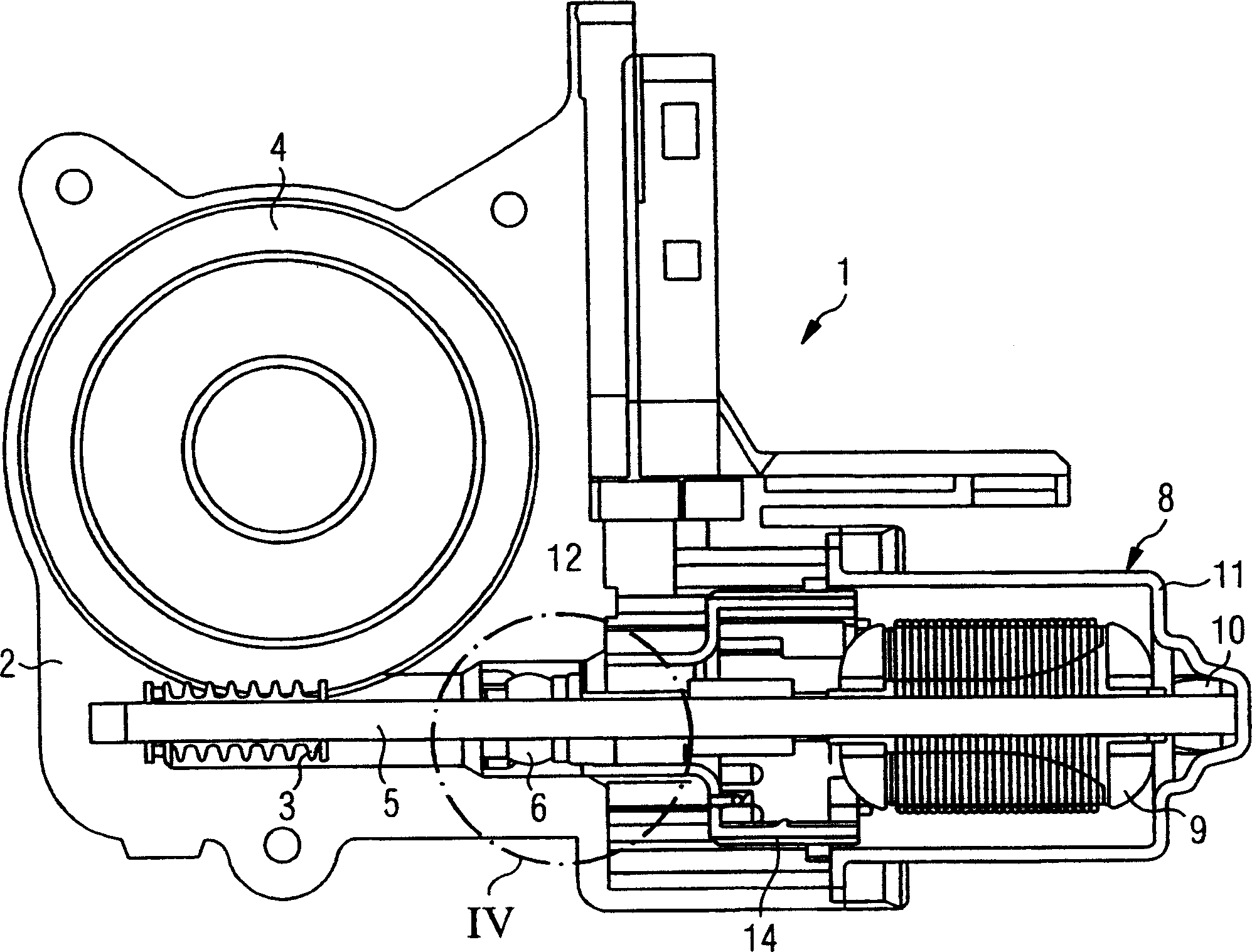
[0040] figure 1 A sectional view of an exemplary actuating drive 1 with a gearbox unit 2 and a motor unit 8 is shown. The gearbox unit 2 has a gearbox housing 12 in which a worm wheel 4 is accommodated and a worm shaft 4 which engages in the worm wheel 4 . The motor unit 8 consists of a motor housing 11 , a rotor 9 accommodated therein with a drive shaft 5 , and a bearing housing 18 at the drive end of the motor unit 8 . The worm shaft 3 is situated on the free end of the drive shaft 5 , which is driven by the motor unit 8 and is partially accommodated in the motor housing 11 . On the motor side, the drive shaft 5 is guided in a bearing 6 opposite the gearbox unit 2 and in a motor end bearing 10 . exist figure 1 In the embodiment of the present invention, the drive shaft 5 is formed in one piece. A two-part embodiment of the drive shaft 5 is likewise conceivable, which has a motor shaft and a transmission shaft and a connection therebetween.

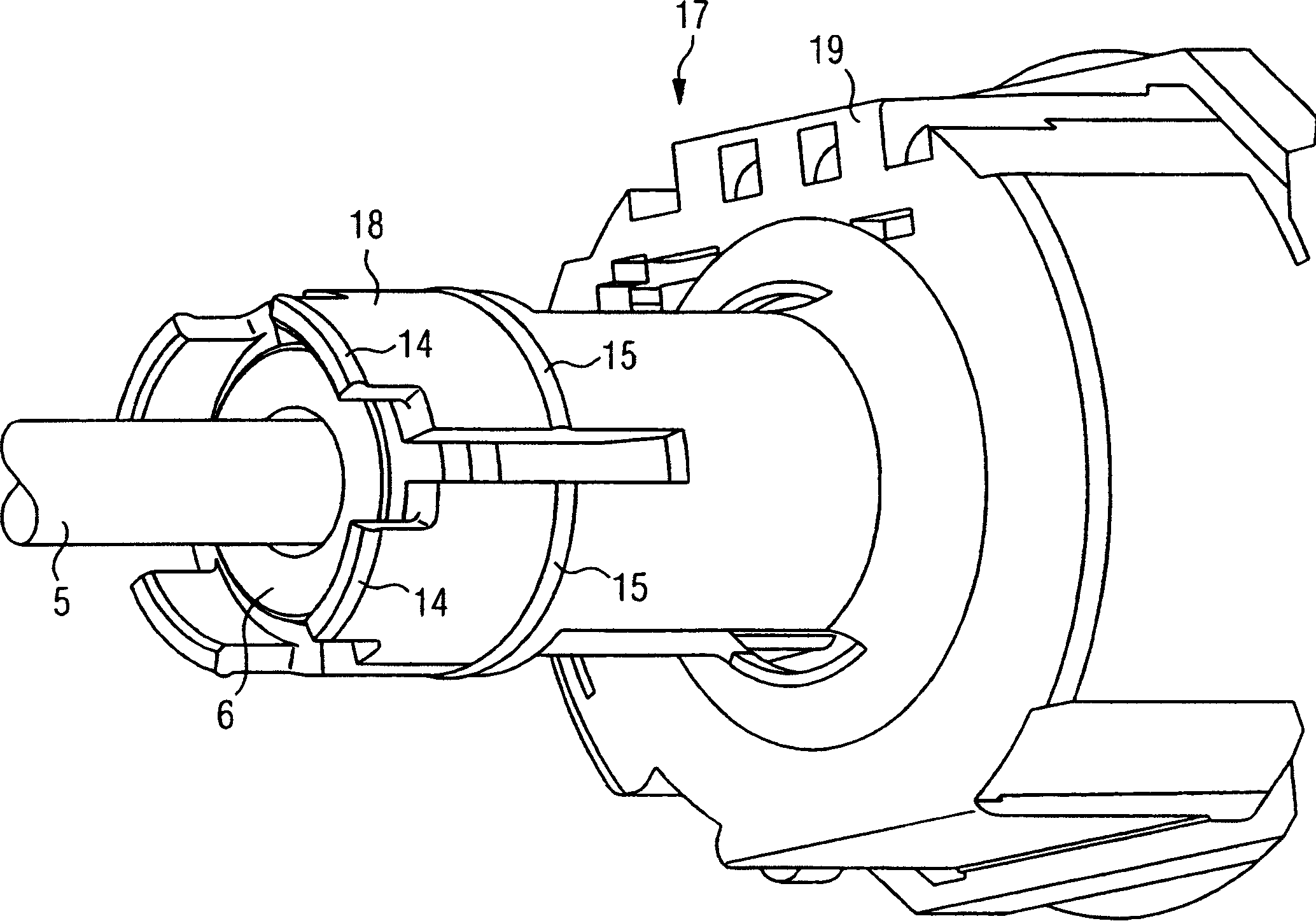
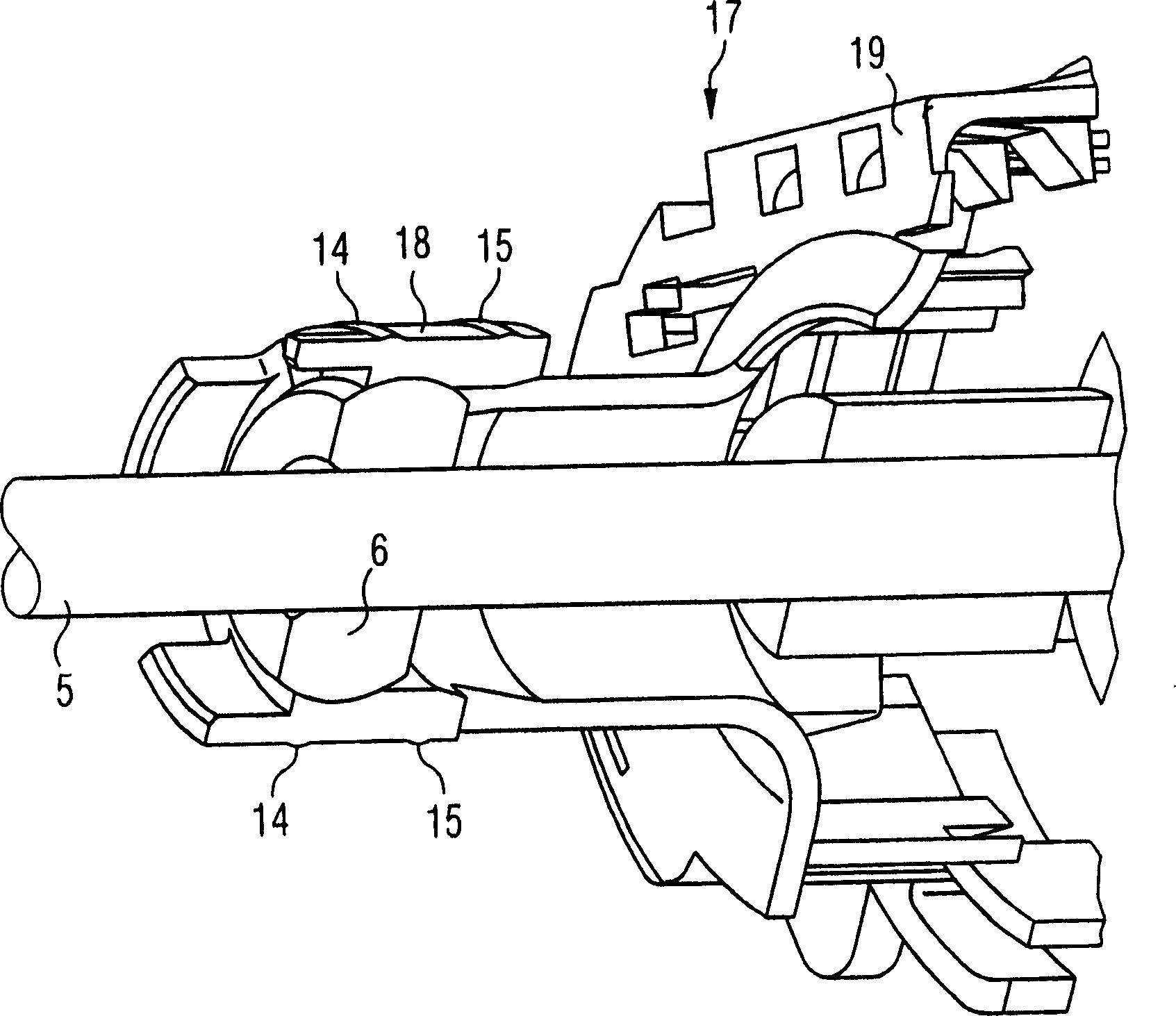
[0041] figure 2 shows a co...


PUM


Abstract

The actuator has a cylindrical bearing housing (18) protruding, along with a bearing and a drive shaft of a rotor, into an opening (7) in a gear housing (21) of a gear unit (2). An outer side of the bearing housing and an inner side of the opening are geometrically mutually harmonized such that clamping points (14, 15) and tension-free places (29) are formed between the bearing housing and the gear housing, when the actuator is assembled. The clamping points exert pre-tensioning force on the bearing through the bearing housing.

Description

technical field [0001] The invention relates to an actuating drive having a gearbox unit and a motor unit. The gearbox unit has a gearbox housing and the motor unit has a motor housing, an inner rotor with a drive shaft and, in particular, a cylindrical bearing housing at the drive end. The bearing housing projects into an opening in the gearbox housing together with a bearing and the drive shaft guided therein. The invention also relates to the application of the servo drive device in automobiles. Background technique [0002] Actuating drives are already known, such as window pane drives or drives for actuating sunroofs. They have a gearbox unit and a motor unit. The gearbox unit has a worm gear and a transmission shaft formed by the worm gear shaft. The motor unit consists of a motor housing, a brush housing and an integrated rotor. The rotor here consists of a so-called rotor pack, which has a number of lamellas fastened to the motor shaft. The transmission shaft a...

Claims


Application Information

Patent Timeline
Patent Type & Authority Applications(China)
IPC IPC(8): H02K7/116F16H57/02F16H57/021F16H57/039
CPCF16C23/04F16H57/039F16H1/16F16H2057/0213F16H57/021Y10T74/18792Y10T74/2186Y10T74/19828
Inventor G·菲尔内克斯K·扎普斯
Owner BROSE FAHRZEUGTEILE GMBH & CO KG HALLSTADT (DE)
Why Eureka
Try Eureka