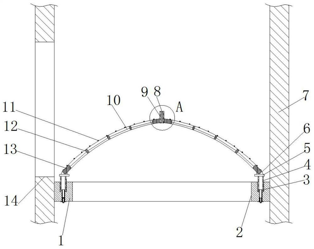
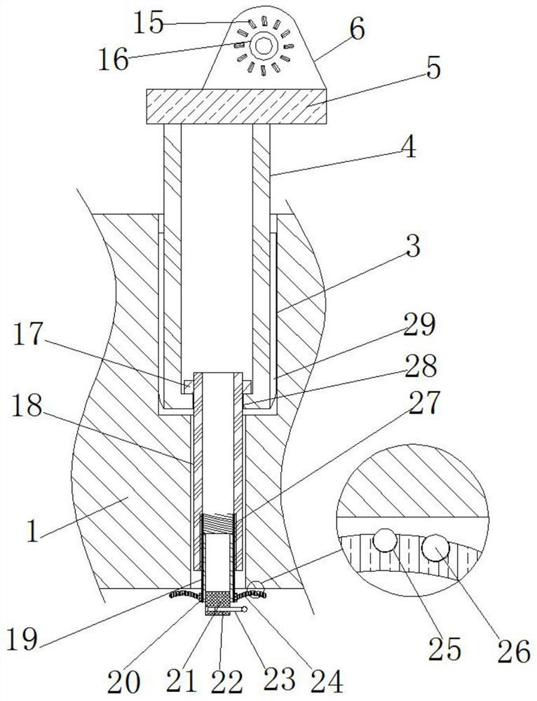
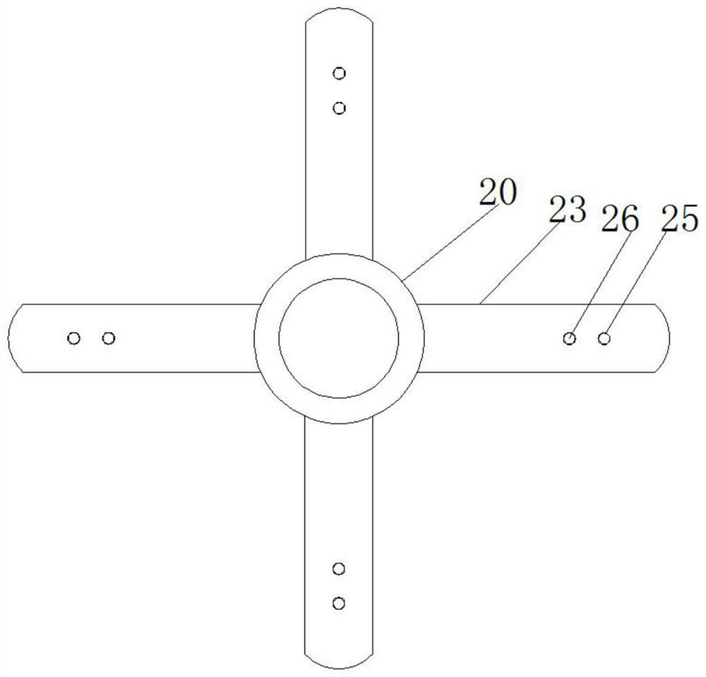
A safety protection device for elevator shafts used in building construction

A safety protection device and building construction technology, which is applied in the processing of building materials, construction, building construction, etc., can solve the problems of non-turnover, increased construction period, and insufficient isolation device, so as to improve stability and safety Effect

Active Publication Date: 2020-10-09
河北天业通建筑工程有限公司
View PDF1 Cites 0 Cited by
  • Summary
  • Abstract
  • Description
  • Claims
  • Application Information

AI Technical Summary

Problems solved by technology

In the construction stage, falling accidents from high places in inner elevator shafts are not uncommon. The "Safety Technical Specifications for Building Construction Work at Heights" stipulates that protective railings or fixed gates must be installed at the head of inner elevator shafts, but traditional elevator shafts are protected by welding steel bars or erecting steel pipes. It is inconvenient, not firm, not beautiful and cannot be turned over. It is not convenient to observe the situation at the side of the elevator shaft or in the shaft. Devices remove waste materials and increase the construction period
[0003] After retrieval, the Chinese patent No. CN201420014918.7 discloses an elevator shaft protection assembly, which includes a hard protection assembly and a soft protection assembly. The hard protection assembly includes a support frame and an isolation layer laid on the plane formed by the support frame. The support frame includes a transverse support end and a longitudinal support end, and the transverse support end includes a first transverse support end and a second transverse support end opposite to the first transverse support end, but the isolation device of the device only The protection door at the wellhead is not strong enough, and secondly, the device does not describe the connection method of the soft protection component and its protection strength

Method used


Image

  • A safety protection device for elevator shafts used in building construction
  • A safety protection device for elevator shafts used in building construction
  • A safety protection device for elevator shafts used in building construction

Examples


Embodiment Construction

[0027] The following will clearly and completely describe the technical solutions in the embodiments of the present invention with reference to the accompanying drawings in the embodiments of the present invention. Obviously, the described embodiments are only some, not all, embodiments of the present invention.

[0028] In describing the present invention, it should be understood that the terms "upper", "lower", "front", "rear", "left", "right", "top", "bottom", "inner", " The orientation or positional relationship indicated by "outside", etc. is based on the orientation or positional relationship shown in the drawings, and is only for the convenience of describing the present invention and simplifying the description, rather than indicating or implying that the referred device or element must have a specific orientation, so as to Specific orientation configurations and operations, therefore, are not to be construed as limitations on the invention.

[0029] refer to Figure ...


PUM


Abstract

The invention belongs to the technical field of elevator shaft protection, particularly relates to a safety device for an elevator shaft for building construction and solves problems of inconvenient installation, insecure installation and inconvenience of observation at an edge of an elevator shaft or in the elevator shaft as traditional elevator shaft protection adopts steel bar welding or steelpipe erection. The device is characterized by comprising a shaft and transversely equally-spaced layers within the shaft, wherein a rectangular wellhead is reserved in the middle of the transverse layer, stepped cylindrical counterbores are reserved on an upper surface of the transverse layer near four corners, support pipes are inserted into the stepped cylindrical counterbores, through holes areformed at the bottom of the support pipes, inner threaded pipes are welded in the through holes, and bottom circumferential inner walls of the inner threaded pipes are screwed with outer threaded pipes. The device is advantaged in that the relatively large pressure from a top end can be borne, the pressure from the top end can be directly distributed above the support pipes at both ends, that middle portions of the two shield plates do not collapse downward when they are pressed again is guaranteed, and safety is improved.

Description

technical field [0001] The invention relates to the technical field of elevator shaft protection, in particular to a safety protection device for elevator shafts used in building construction. Background technique [0002] With the rapid development of my country's economy, there are more and more high-rise buildings. In the construction stage, falling accidents from high places in inner elevator shafts are not uncommon. The "Safety Technical Specifications for Building Construction Work at Heights" stipulates that protective railings or fixed gates must be installed at the head of inner elevator shafts, but traditional elevator shafts are protected by welding steel bars or erecting steel pipes. It is inconvenient, not firm, not beautiful and cannot be turned over. It is not convenient to observe the situation at the side of the elevator shaft or in the shaft. Devices remove waste materials one by one and increase the construction period. [0003] After retrieval, the Chin...

Claims


Application Information

Patent Timeline
Patent Type & Authority Patents(China)
IPC IPC(8): E04G21/32
CPCE04G21/32E04G21/3204
Inventor 刘志斌路卫兵杨利明李大澎杨利飞高智侯小博武永峰杨阳武振宇胡建伟武会刚李有军武晓杰马秀辉
Owner 河北天业通建筑工程有限公司
Why Eureka
Try Eureka