Network and its management method
A network and management server technology, applied in the field of network and its management, can solve problems such as difficulty in interchangeable frequency band communication speed, increase of wireless LAN equipment or mutual interference of application methods, slow response, etc.
Inactive Publication Date: 2007-01-17
FURUNO ELECTRIC CO LTD +1
0 Cites 0 Cited by
AI-Extracted Technical Summary
Problems solved by technology
[0011] (1) Even if the aforementioned functions for preventing interference with existing wireless LAN devices are used, mutual interference may occur depending on the size of the wireless LAN device or the method of operation
[0012] (2) Wireless space cannot be used effectively and wastes a lot
so the response becomes slower
[0013] (3) When a certain problem occurs on the network used by the wireless LAN, the other party who should adjust it is not clear
[0014] (4) Even if you know the interference with other nearby wireless LAN devices, it is easy to leak mutual secrets when adjusting with the other party
[0015] (5) Depending on the usage status of the wireless LAN, the frequency band (communication speed), etc. are diffi...
Abstract
The present inventon provided a highly convenient network by eliminating the problems of interference, leak, tapping, and band occupation, and the problem of network connection to one's own system in a shared space, and to provide its management method. A management server 1 registers relating information between additional information such as a VLAN tag or VPN header to be added to a packet and identification information such as an SSID, and writes the relating information in whole radio access points 3a-3d. Radio terminals 5a-5c, 5a', 5b' performs radio communication with one of the access points 3, so that the additional information such as the VLAN tag related to the identification information such as the SSID is added to the packet and transmitted to a backbone. On the contrary, when the communication is performed with the applicable radio terminal by using the identification information corresponding to the additional information of the packet received from the LAN in the system, the terminal becomes communicable with a server, etc. , which is connected to the LAN of one's own system.
Application Domain
Data switching by path configuration
Technology Topic
Radio accessRadio access point +3
Image
Examples
- Experimental program(2)
Example Embodiment
[0067] The network of Embodiment 1 employs SSID and VLAN, effectively utilizes the wireless space, communicates between the wireless terminal and the node connected to the LAN of the unit to which it belongs, and makes it set and operate as follows.
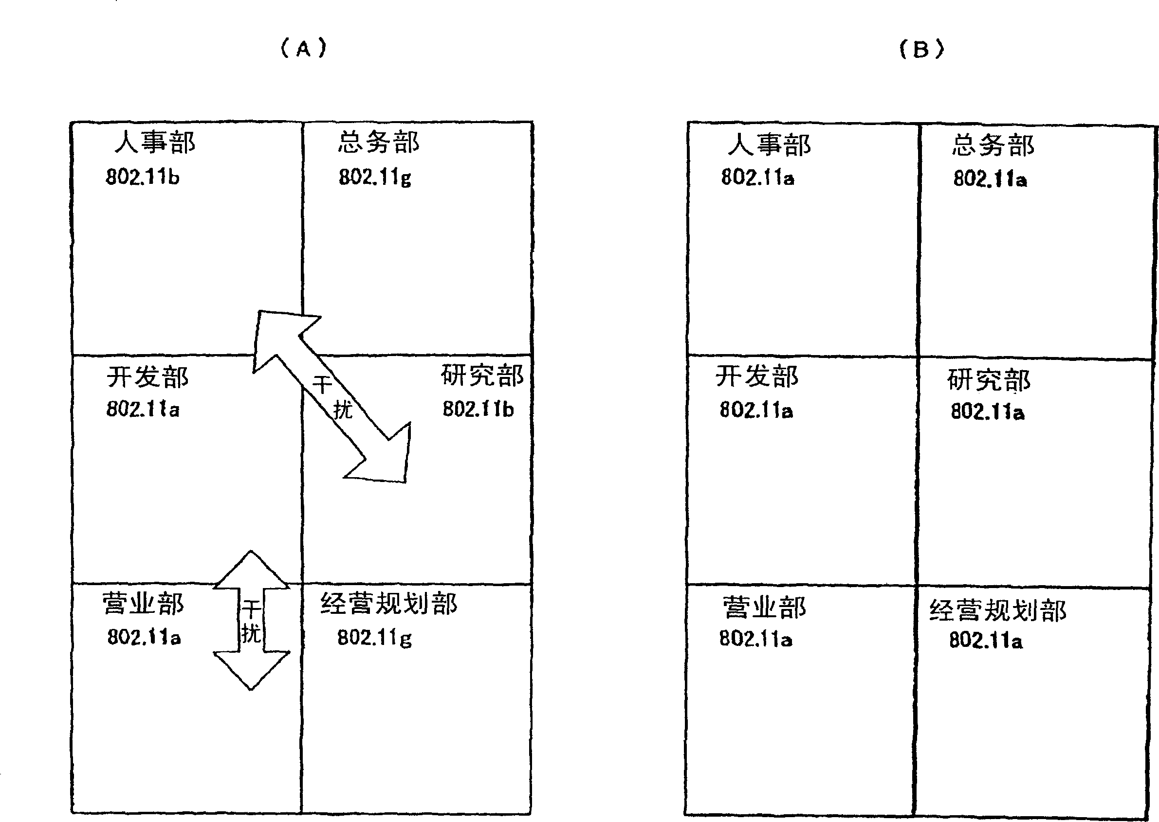
[0068] (1) An SSID is assigned to each unit that is divided.
[0069] (2) A virtual LAN (hereinafter abbreviated as 'VLAN') is assigned to each divided unit.
[0070] (3) Assign a management VLAN (for example, 'VLAN2') to the management server.
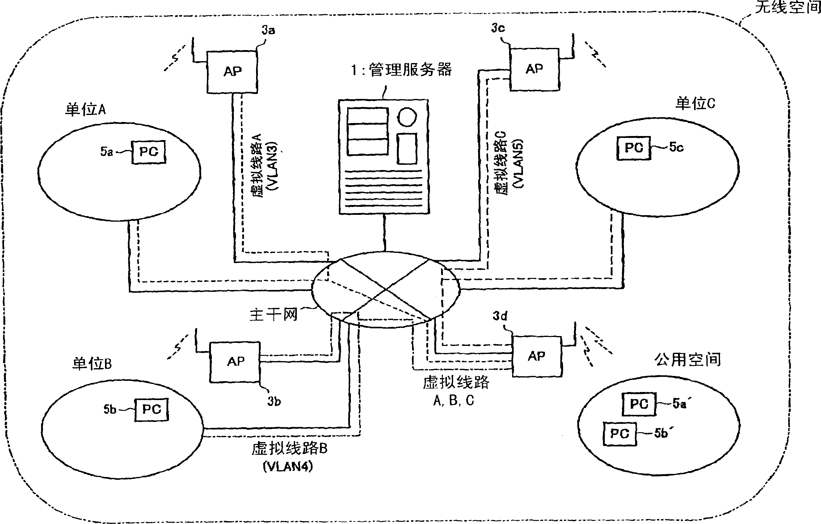
[0071] (4) Build a backbone LAN for wireless LAN.
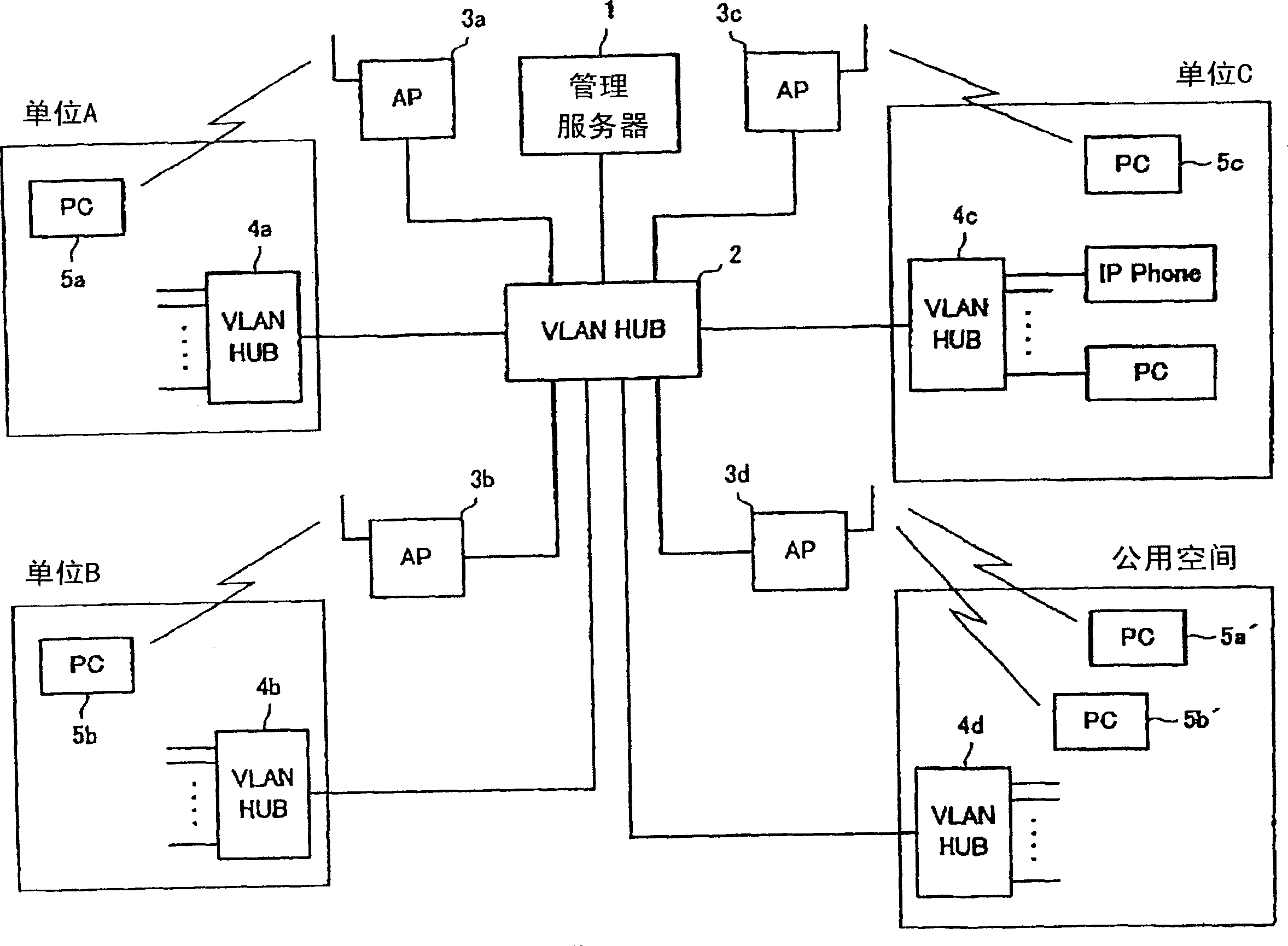
[0072] A wireless access point (hereinafter abbreviated as 'AP') is installed together on a wired communication network for a wireless LAN that can recognize a VLAN tag. AP is not bound by unit, and can be configured and set for wireless communication with the best communication quality.
[0073] (5) The wired LAN and wireless LAN of each unit are connected with the backbone LAN.
[0074] The connection point of the backbone LAN for wired LAN and wireless LAN in each unit is set to receive the information packet with the VLAN tag of the unit, and remove the VLAN tag to return the status of the packet on the standard LAN. It can be sent to the wired LAN in the unit The device with the sending function (usually a switch center or L3 switch with VLAN function). In addition, this device attaches the VLAN tag of the unit to the packet sent to the wireless LAN.
[0075] (6) The AP communicates with the SSID and the VLAN flag.
[0076] The AP follows the instructions of the management server that communicates in the above-mentioned 'VLAN2', and the SSID and VLAN are associated with each other.
[0077] E.g,
[0078] The information packet from 'VLAN3' is sent to the wireless terminal of SSIDA, and the information packet from SSIDA is sent to 'VLAN3'.
[0079] The information packet from 'VLAN4' is sent to the wireless terminal of SSIDB, and the information packet from SSIDB is sent to 'VLAN4'.
[0080] The information packet from 'VLAN5' is sent to the wireless terminal of SSIDC, and the information packet from SSIDC is sent to 'VLAN5'.
[0081] VLAN2 is used as a communication LAN for management, and is used by the AP itself.
[0082] (7) The wireless terminal communicates according to the SSID of the unit to which it belongs.
[0083] That is,
[0084] Wireless terminals belonging to unit A perform communication according to SSIDA.
[0085] Wireless terminals belonging to unit B perform communication according to SSIDB.
[0086] Wireless terminals belonging to unit C perform communication according to SSIDC.
[0087] In this way, it is possible to connect to the LAN of the own unit regardless of which access point is connected.
[0088] Because this relationship does not change even in the public space, everything in the room of the unit remains unchanged within the scope of overall management of the radio, and it can be used as it is.
[0089] (8) The management server manages the wireless status and each VLAN.
[0090] The management server performs the following processing.
[0091] Manage the backbone network, AP, and wireless space.
[0092] Manage the correlation between SSID and VLAN.
[0093] Check the usage status of VLAN assigned to each unit.
[0094] Charge data is compiled based on the usage status.
[0095] Hereinafter, a specific configuration for realizing the above-mentioned structure is shown.
[0096] figure 2 It is a diagram showing the overall configuration of the network. In the figure, VLAN-HUB2 is a HUB constituting a backbone LAN connected to other VLAN-HUBs 4 a to 4 d , wireless access points 3 a to 3 d , and management server 1 .
[0097] VLAN-HUB4a is the hub used by unit A, connected to other common (not corresponding to VLAN) hubs or nodes of personal computers, etc. VLAN-HUB4b, 4c are also used by unit B and unit C, connected to other common hubs or nodes. VLAN-HUB4d is a HUB used in the public space, where wired terminals (such as personal computers) of each unit are connected.
[0098] Notebook computers 5a, 5b, 5c, 5a', 5b' serving as wireless terminals perform wireless communication with any of the access points 3a to 3d, and function as one node of the LAN in the own unit. For example, as long as the notebook computers 5a, 5a' belong to the unit A, they can communicate between nodes (such as servers) on the LAN connected to the VLAN-HUB 4a of the unit A by using the access point 3d to communicate. Similarly, the notebook computers 5b, 5b' belonging to the unit B can communicate between nodes (such as servers) on the LAN connected to the VLAN-HUB 4b of the unit A by communicating through the access point 3d.
[0099] image 3 A schematic diagram representing a virtual circuit of a network. As long as the notebook computers 5a and 5a' as wireless terminals belong to the unit A, they are respectively connected to the LAN in the unit A through the virtual line (VLAN3). In addition, as long as the notebook computers 5b, 5b' belong to the unit B, they are respectively connected to the LAN in the unit B through the virtual line (VLAN4). Similarly, as long as the notebook computer 5c belongs to the unit C, it is connected to the LAN in the unit C through a virtual line (VLAN5).
[0100] In this way, wireless terminals belonging to each unit are respectively connected to LANs in each unit by using the backbone LAN and the VLAN function of the VLAN-HUB provided in each unit. Therefore, the correlation information between the VLAN tag and the wireless identification number SSID is written in advance in the access points 3a to 3d of each wireless LAN.
[0101] Figure 4 It is a diagram showing the relationship between the VLAN tag and the SSID that are set in advance in the management server 1 . In this embodiment, since three units (unit A to unit C) are managed, three sets of VLAN flags and SSID groups are registered in advance.
[0102] Figure 5 It is the communication quality (QoS) per unit, the communication packet volume and the data charged accordingly managed by the management server 1 . For example, QoS is set according to the level of communication quality subscribed in advance. In addition, the packet volume data of the wireless access point is taken out to obtain the charging data corresponding to it.
[0103] Image 6 Indicates the difference between a normal packet transmitted on the Internet (registered trademark) and a packet constituting a VLAN. (A) is a normal packet, basically adding an Internet (registered trademark) header to an IP packet having an IP header and a real data portion. On the contrary, a packet for a VLAN is formed, and a VLAN flag is added thereto. This VLAN tag is a tag for identifying each group for setting a virtual group of terminals independently of the physical connection form.
[0104] Figure 7 ~ Figure 11 Shows the main processing contents of the management server, access point, and nodes of each unit's wired LAN in the form of a flowchart.
[0105] Figure 7 It is a flow chart for setting information related to VLAN flag and SSID. The management server writes a pair of VLAN tags and SSIDs entered externally (console) into Figure 4 The interrelated information table shown (updated). Then, the above-mentioned interrelated information is written to all access points (APs). This interrelated information is stored by this access point.
[0106] Figure 8 It is a flowchart showing communication processing between a wireless terminal and an access point.
[0107] The wireless terminal accesses the access point according to the SSID set on the wireless terminal and performs wireless communication. In this way, the access point sends the packet with the VLAN tag corresponding to the SSID received from the wireless terminal to the backbone LAN.
[0108] Figure 9 It is a flowchart showing the procedure of communication processing between the wired LAN nodes and the access points of each unit. When an information packet with a VLAN tag is sent from a wired LAN node of a certain unit to the access point, the access point removes the VLAN tag from the information packet and restores it to a normal information packet, and at the same time performs wireless communication with the wireless terminal according to the SSID.
[0109] In this way, the wireless terminal can communicate with the nodes of the wired LAN of its own unit no matter which access point it passes through. Therefore, for example, even if a wireless terminal belonging to unit A is used in the room of unit B, the wireless terminal can communicate with the nodes of unit A's wired LAN.
[0110] Figure 10 This is a flowchart showing the processing contents of communication quality setting by the management server. First read the QoS of each SSID input from the outside (console, etc.), write it (update) Figure 5 shows the control information table. Then, the above-mentioned QoS information is written to all access points.
[0111] Through this, the wireless terminal can perform wireless communication with the QoS corresponding to its SSID
[0112] Figure 11 It is a flowchart showing the processing contents of charge management by the management server. The management server calculates charges based on QoS and packet volume, or based on fees (process (コ-ス)). According to the instructions from the outside, the above-mentioned charging information is sent to the email address specified by the customer. Or deduct from the bank debit account designated by the customer.
[0113] Below, refer to Figure 12 to Figure 15 A network according to Embodiment 2 will be described.
Example Embodiment
[0114] The network according to Embodiment 2 is a combination of user authentication based on IEEE802.1X and VLAN. Therefore, it is set and operated as follows.
[0115] (1) An SSID is assigned to each divided unit.
[0116] (2) A virtual LAN (hereinafter abbreviated as 'VLAN') is assigned to each divided unit.
[0117] (3) Assign a management VLAN (for example, 'VLAN2') to the management server.
[0118] (4) Build a backbone LAN for wireless LAN.
[0119] A wireless access point (hereinafter abbreviated as 'AP') is installed together on a wired communication network for a wireless LAN that can recognize a VLAN tag. Even if it is installed in each unit and in a common space, it is installed in the same way. AP is not bound by unit, and can be configured and set for wireless communication with the best communication quality.
[0120] (5) The wired LAN and wireless LAN of each unit are connected with the backbone LAN.
[0121] The connection point of the backbone LAN for wired LAN and wireless LAN in each unit is set to receive the packet with the VLAN tag of the unit, and remove the VLAN tag to return the status of the packet on the standard LAN. It can be sent to the wired LAN in the unit. The device with the sending function (usually a switch center or L3 switch with VLAN function). In addition, this device attaches the VLAN tag of the unit to the information packet sent to the wireless LAN.
[0122] (6) Each user has a user ID and an authentication key for connecting to the wireless LAN. Each user has a user ID and an authentication key in the form of 'user name@unit domain name'. Typical authentication keys are passwords, places of birth, one-time passwords, electronic certificates, and the like. For example, the user ID of the user ID "taro" (Taro-kun) belonging to unit A is "taro@A".
[0123] (7) The AP performs user ID authentication.
[0124] Authenticate wirelessly connected terminals in accordance with IEEE802.1X. At this time, by looking at the domain name of the user ID, determine a certain VLAN of the RADIUS server that inquired about the authentication key or a VLAN connected after authentication. The relationship between domain names and VLANs is subject to the instructions of the management server communicating through 'VLAN2'.
[0125] Assume that unit A is its own unit holding an authentication server based on electronic certificates, and others based on password authentication. When entrusting authentication to authentication, it is as follows.
[0126] When the wireless terminal obtains the connection by user ID "taro@A", for example, the AP communicates with the management server connected with the domain name A of the unit area and VLAN2. In this way, authentication via 'VLAN3' is instructed, and based on this, the authentication key is determined by communicating with the authentication server of unit A across VLAN3.
[0127] Also, when the wireless terminal obtains the connection by user ID "jiro@B", for example, the AP communicates with the management server connected to the unit domain name B and "VLAN2". In this way, authentication via 'VLAN6' is instructed, and the authentication key is determined by communicating with the authentication server for entrusting authentication across "VLAN6".
[0128] (8) The AP associates the domain name of the unit and the VLAN flag with each other and communicates.
[0129] Packets from 'VLAN3' are sent to wireless terminals authenticated in unit area A, and packets from wireless terminals authenticated in unit area A are sent to VLAN3.
[0130] Packets from 'VLAN4' are sent to wireless terminals authenticated in unit area B, and packets from wireless terminals authenticated in unit area B are sent to VLAN4.
[0131] Packets from 'VLAN5' are sent to wireless terminals authenticated in unit area C, and packets from wireless terminals authenticated in unit area C are sent to VLAN5.
[0132] VLAN2 is used as a communication LAN for management, and is used by the AP itself.
[0133] (9) Wireless terminal user ID and authentication key authentication, communicate with public SSID.
[0134] Wireless terminals belonging to unit A are authenticated with user IDs including unit area A, and communicate with a common SSID. In this way, the wireless terminal can connect to the LAN of its own unit regardless of which access point it is connected to.
PUM


Description & Claims & Application Information
We can also present the details of the Description, Claims and Application information to help users get a comprehensive understanding of the technical details of the patent, such as background art, summary of invention, brief description of drawings, description of embodiments, and other original content. On the other hand, users can also determine the specific scope of protection of the technology through the list of claims; as well as understand the changes in the life cycle of the technology with the presentation of the patent timeline. Login to view more.