
Method and device for equalizing tension in parallel yarns

A technology of parallel fiber and operating mode, which is applied in the direction of transportation and packaging, other manufacturing equipment/tools, textiles and paper making, and can solve problems such as uneconomical and inability to adjust creel tension

Inactive Publication Date: 2007-01-24
凯特斯管理有限公司 +1
View PDF2 Cites 3 Cited by
  • Summary
  • Abstract
  • Description
  • Claims
  • Application Information

AI Technical Summary

Problems solved by technology

[0007] It is not economical to control the output of the creel with many end brakes
And it should be noted that this method can only control the output of the creel and cannot adjust the tension of the creel on the fiber

Method used


Image

  • Method and device for equalizing tension in parallel yarns
  • Method and device for equalizing tension in parallel yarns
  • Method and device for equalizing tension in parallel yarns

Examples


Embodiment Construction

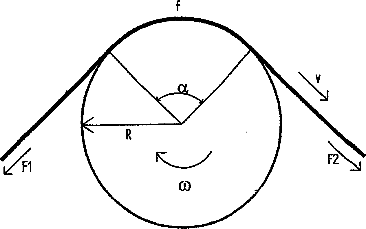
[0056] figure 1 The fiber tow is shown moving at a specific velocity (v) on a driven roller while the fiber tow partially surrounds the roller at an angle (α). The roller rotates at a peripheral speed (ω×R) and in the direction shown on the diagram. The friction coefficient of the roller surface is (f). F1 is the tension of the fiber bundle in front of this roller. F2 is the tension of the fiber bundle behind the roller

[0057] One of three things will now happen:

[0058] 1. (ω×R) > v

[0059] The peripheral speed of the roller is greater than that of the fiber bundle, so the tension on the fiber bundle is reduced. Since sliding friction and sliding velocity are independently separated, the difference in velocity between the fiber and the roller surface is not important. This phenomenon occurs at the tension reducing device.

[0060] (F1>F2).

[0061] 2. (ω×R)=v

[0062] The peripheral speed of the roller is equal to the speed of the fiber bundle, and the fiber bund...


PUM


Abstract

The invention is concerned with a mode of operation and a construction to bring parallel fibres, threads or yarns (12) from different delivery points and with individual unequal exit force to the same tension each with the others. The invention consists of three processing steps: Decreasing the tension of the fibres (12) from an arbitrary individual tension level to tension level nil. Slippage-free transport of the fibres through a slip lock unit with a known velocity determined beforehand. Increasing the tension of each and every fibre from tension level nil to the required collective tension level.

Description

technical field [0001] This invention is about how to unwind the spools, bobbins, spinning shafts and spin cakes from the creel and put all the yarns under the same correct tension on each other to get them into the thread For further processing purposes in textile machines. Background technique [0002] In the manufacture of textiles, especially when dealing with high-quality fibers such as glass fiber and carbon fiber, how to make the tension between the fibers the same as the finished product is very important. After all, when manufacturing semi-finished or finished textile products, there is usually a pre-tension force between the fibers, which eventually disappears due to fiber shrinkage when the textile is finished. If the fibers have different diameters, usually as in spun threads, the disappearance of this pre-tension force will produce different shrinkage rates among the individual fibers after the product is processed. This will affect the flatness of the finishe...

Claims


Application Information

Patent Timeline
Patent Type & Authority Applications(China)
IPC IPC(8): B65H59/14B65H51/10B65H59/18B65H59/28B65H59/38D02H13/26
CPCB65H59/388B65H2701/31B65H59/18B65H59/28D02H13/26B65H2701/38B65H51/105B65H59/10B65H59/14
Inventor 凡恩德宏恩·鲁道夫·瓊恩斯·哥兰德斯·安东尼斯
Owner 凯特斯管理有限公司
Learn More