MRI guiding high intensity focusing ultrasonic therapeutic system

A focused ultrasound and treatment system technology, applied in the field of medical devices, can solve the problems of limited movable height, great difficulty, affecting the treatment process, etc., and achieve the effect of reducing the non-magnetic requirement, improving the utilization rate, and improving the treatment effect.

Active Publication Date: 2007-01-31
RONGHAI SUPERSONIC MEDICINE EN
View PDF4 Cites 19 Cited by
  • Summary
  • Abstract
  • Description
  • Claims
  • Application Information

AI Technical Summary

Problems solved by technology

[0002] Focused ultrasound treatment in the prior art mostly adopts B-ultrasound equipment for positioning and monitoring treatment, and adopts this B-ultrasound equipment for monitoring and treatment. Ultrasound system still has certain limitations in its visible area; 2. The observable depth of ultrasound images is limited, and bony substances have a particularly large impact on the images, and the tissue behind the bone can hardly be observed, and there are artifacts; 3. Ultrasound images Poor ability to identify tissue boundaries, especially for small tumors and deep tumors
[0008] The above-mentioned patents are all combined treatment systems using MRI devices and ultrasonic treatment equipment. These treatment systems mainly have the following disadvantages: 1) Since the movable height under the MRI treatment bed is very limited, ultrasonic transducers are arranged under it for multiple coordinates. Exercise is very difficult, and it is even more difficult to arrange a complex motion positioning mechanism. After the motion positioning mechanism is arranged under the treatment bed of the MRI hole, it occupies the limited movement space of the ultrasonic transducer, thus affecting the quality of the treatment process. 2) These systems require high-demand non-magnetization design and processing of the ultrasonic transducer and its motion positioning device, which increases technical complexity and cost; 3) Driven by the motion positioning mechanism, the ultrasonic transducer The device can only carry out limited movement, and cannot adapt to the multi-directional requirements of the treatment of tumors and other diseases, and because the ultrasonic transducer cannot rotate, the ultrasonic transducer can only perform bottom-up treatment under the treatment bed. There is nothing that can be done if the treatment is performed from top to bottom; 4) It is difficult for the operator to perform assisted manual operation, which is not conducive to the operator's clinical observation

Method used


Image

  • MRI guiding high intensity focusing ultrasonic therapeutic system
  • MRI guiding high intensity focusing ultrasonic therapeutic system
  • MRI guiding high intensity focusing ultrasonic therapeutic system

Examples


Embodiment 1

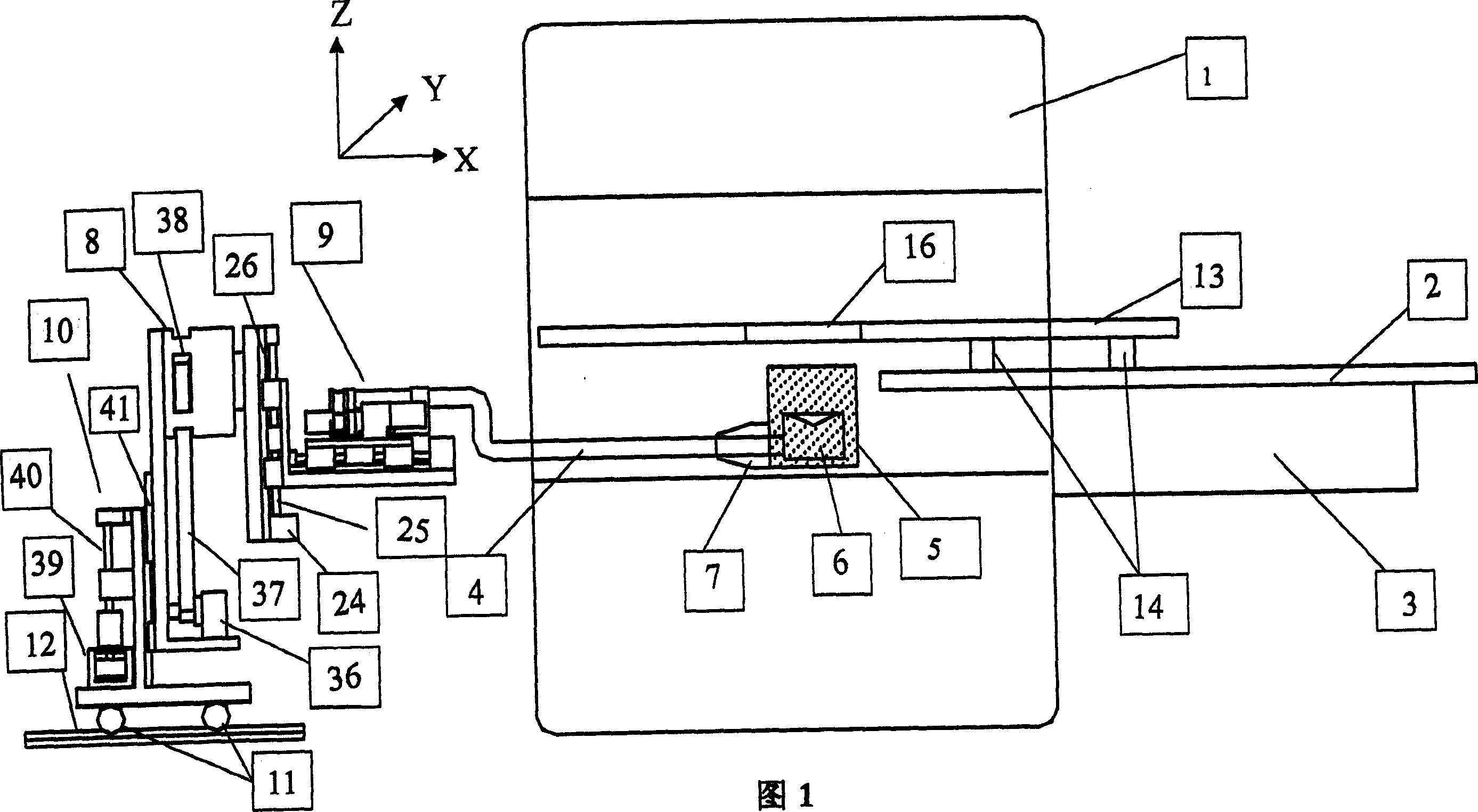
[0035] As shown in FIG. 1 , the system in this embodiment includes an MRI device 1 and a high-intensity focused ultrasound therapy device. Wherein, the high-intensity focused ultrasound treatment device includes an ultrasonic transducer 6 and a motion positioning mechanism, which is located at the rear of the MRI device, and a support rod 4 is connected to the motion positioning mechanism. One end of the support rod 4 is connected with the control device 9 in the motion positioning mechanism, and the other end is connected with the ultrasonic transducer 6 . The motion positioning mechanism includes a control device 9 , driven by the control device 9 , the support rod 4 can move in X, Y, Z directions and rotate around the X direction.

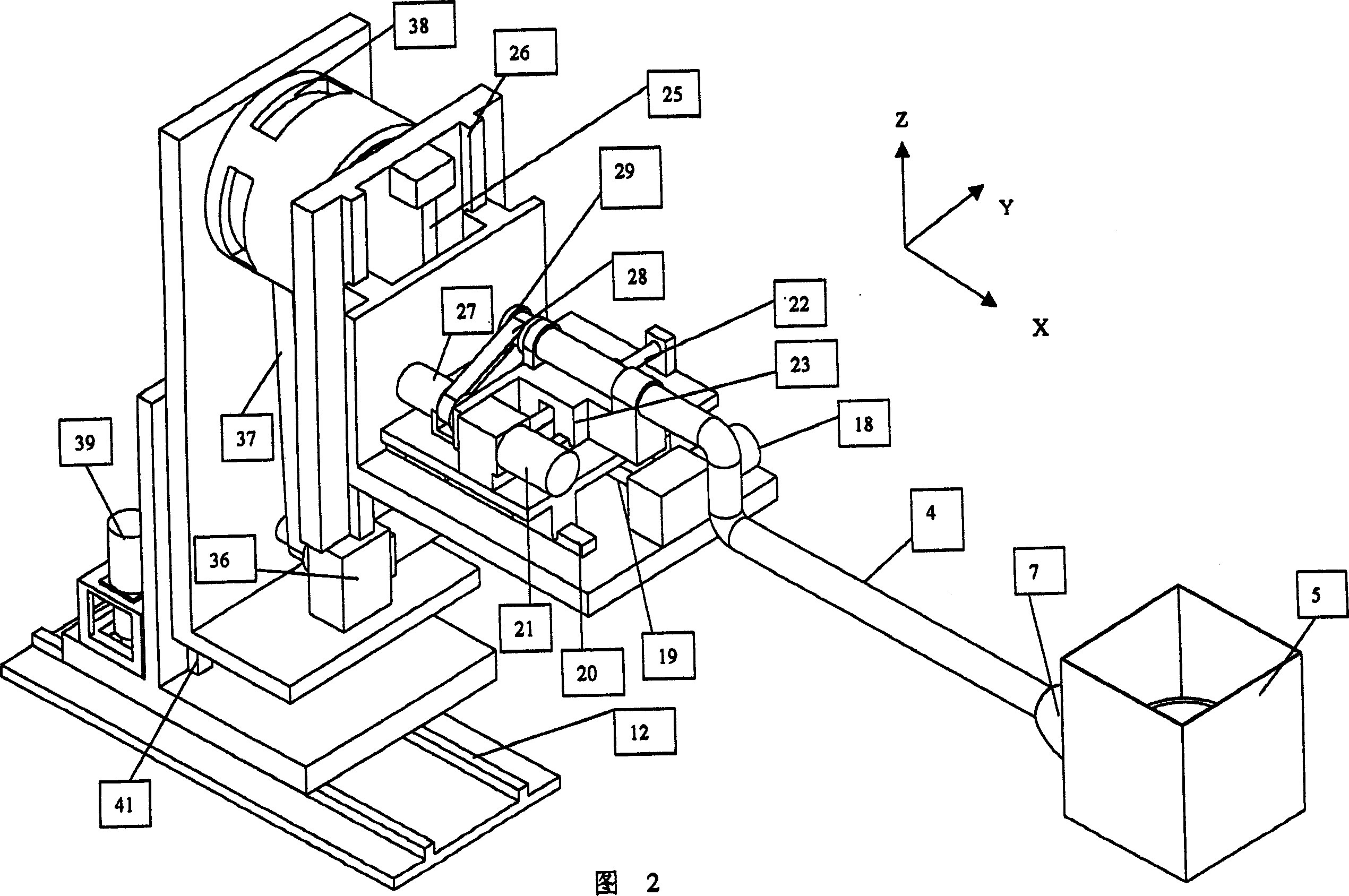
[0036] As shown in Figures 1 and 2, the structure of the control device 9 moving along the X, Y, and Z directions respectively includes a motor, a screw rod, a slider and a slide rail connected with the support rod, and the screw rod is connecte...

Embodiment 2

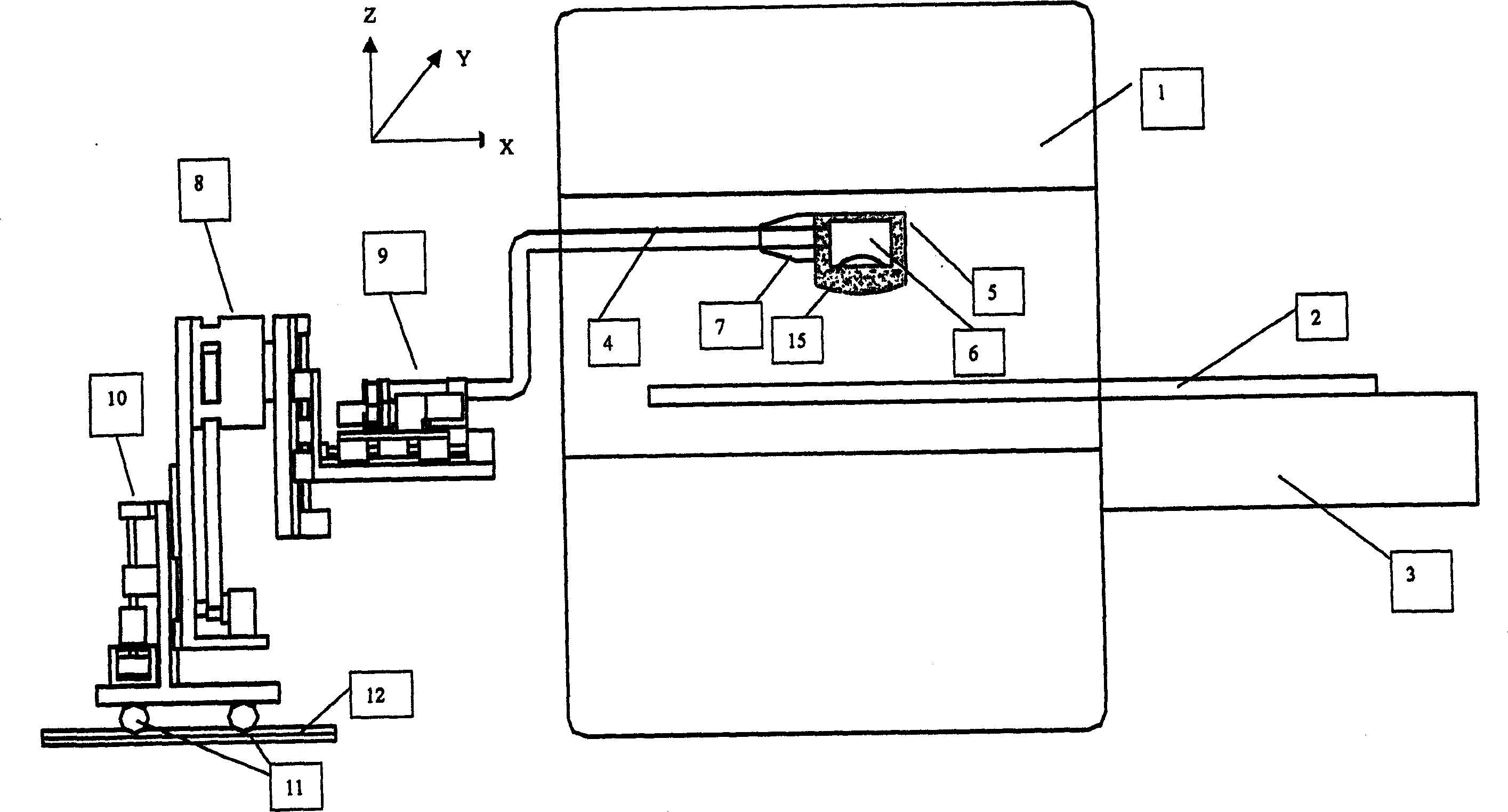
[0048] like image 3 As shown, in this embodiment, the motion positioning mechanism is located at the rear of the MRI apparatus 1 . The difference from Embodiment 1 is that in this embodiment, there is only the first treatment couch 2 in the aperture of the MRI apparatus 1 , and the ultrasonic transducer 6 is located above the first treatment couch 2 to apply ultrasound to the patient's lesion from top to bottom for treatment. In the MRI device 1, since the ultrasonic transducer 6 is located above the treatment bed body and applies ultrasonic waves to the patient's lesion from top to bottom for treatment, there may be no small holes in the first treatment bed 2, and the first treatment bed 2 can be selected. Treat normally.

[0049] The fluid container 5 adopts a water bag, and the water bag is filled with degassed water. In order to prevent the degassed water in the water bag from flowing out, the open end of the water bag is closed by a flexible sound-transmitting film 15. T...

Embodiment 3

[0052] like Figure 4 , 5 As shown, in this embodiment, the motion positioning mechanism is located at the front of the MRI apparatus 1 during treatment, and the MRI apparatus includes a first treatment couch 2 and a second treatment couch 13 . The motion positioning mechanism includes a bed motion device for moving the second treatment bed 13 and a control device 9 for controlling the ultrasonic transducer to rotate in X, Y, Z and X directions. The second treatment bed 13 is connected to the motion positioning mechanism through the bed motion device.

[0053] Among them, the structure of the control device 9 is the same as that in the first embodiment.

[0054] The bed moving device includes a pulley slide rail structure for making the second treatment bed 13 move left and right and a pulley structure for making the second treatment bed 13 move back and forth.

[0055] like Figure 4 As shown, the sliding rail 17 is fixed on the control device 9, the fluid device 5 is pla...


PUM


Abstract

A MRI guided high-intensity focused ultrasonic therapy system is composed of a MRI unit including the first therapeutic bed and a high-intensity focused ultrasonic therapy unit having an ultrasonic transducer and a moving-locating mechanism with a supporting rod able to be extended in the gap of said MRI unit during therapy and connected to said ultrasonic transducer.

Description

technical field [0001] The invention belongs to the technical field of medical devices, and relates to an ultrasonic treatment system, in particular to an MRI-guided high-intensity focused ultrasonic treatment system. Background technique [0002] Focused ultrasound treatment in the prior art mostly adopts B-ultrasound equipment for positioning and monitoring treatment, and adopts this B-ultrasound equipment for monitoring and treatment. Ultrasound system still has certain limitations in its visible area; 2. The observable depth of ultrasound images is limited, and bony substances have a particularly large impact on the images, and the tissue behind the bone can hardly be observed, and there are artifacts; 3. Ultrasound images The ability to identify tissue boundaries is poor, especially for small tumors and deep tumors. [0003] In addition, an important application in biology and medicine is the MRI (Magnetic Resonance Imaging Magnetic Resonance Imaging) device, which can...

Claims


Application Information

Patent Timeline
Patent Type & Authority Applications(China)
IPC IPC(8): A61N7/00A61N7/02A61B5/055A61B17/225A61B17/22
CPCA61N7/02A61B2019/5236A61B2090/374
Inventor 汪龙古月木木付兵汪海
Owner RONGHAI SUPERSONIC MEDICINE EN
Why Eureka
Try Eureka