Image capturing apparatus and image capturing method
A technology of camera device and camera unit, which is applied in image analysis, image communication, image data processing, etc., and can solve problems such as angle of view, inconsistency of aperture value in focus state, few images obtained, and difficulty in synchronizing optical devices.
- Summary
- Abstract
- Description
- Claims
- Application Information
AI Technical Summary
Problems solved by technology
Method used
Image
Examples
no. 1 example
[0054] The structure of the camera
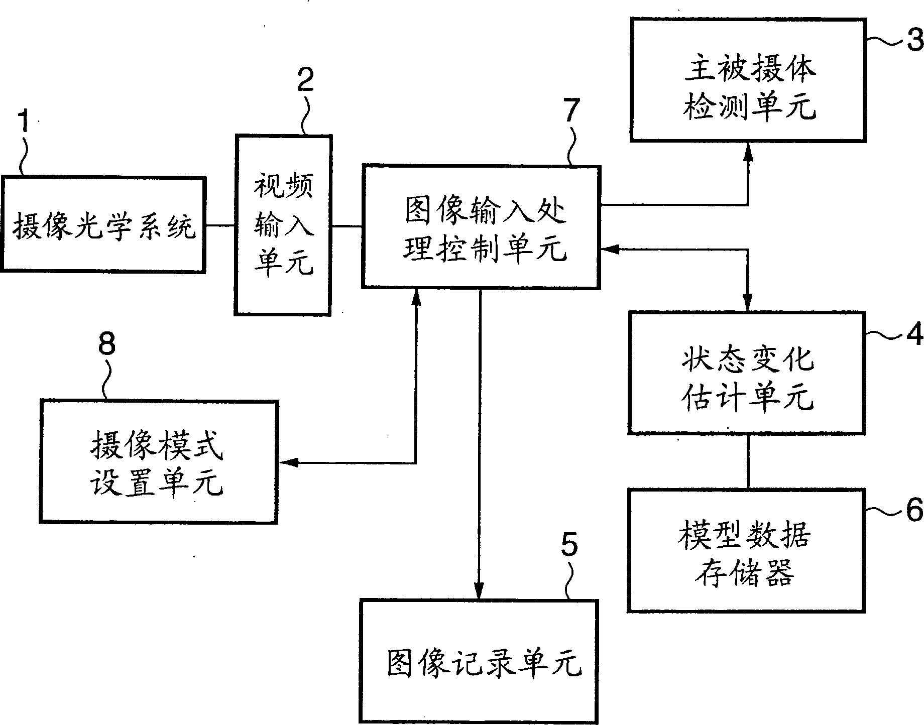
[0055] reference figure 1 The structure of the imaging apparatus according to the first embodiment is described. figure 1 It is a block diagram showing the structure of the main part of the imaging apparatus according to the first embodiment.
[0056] Such as figure 1 As shown, the imaging device according to the first embodiment includes: an imaging optical system 1, a video input unit 2, a main subject detection unit 3, a state change estimation unit 4, a model data memory 6, an image input processing control unit 7, a camera Mode setting unit 8, image recording unit 5, etc. The outline of the function of each constituent unit is as follows.
[0057] The imaging optical system 1 includes a lens and the like, and forms an image based on light propagating from a subject.
[0058] The video input unit 2 photoelectrically converts the image formed by the imaging optical system 1 and outputs the image as image data. The video input unit 2 is co...
no. 2 example
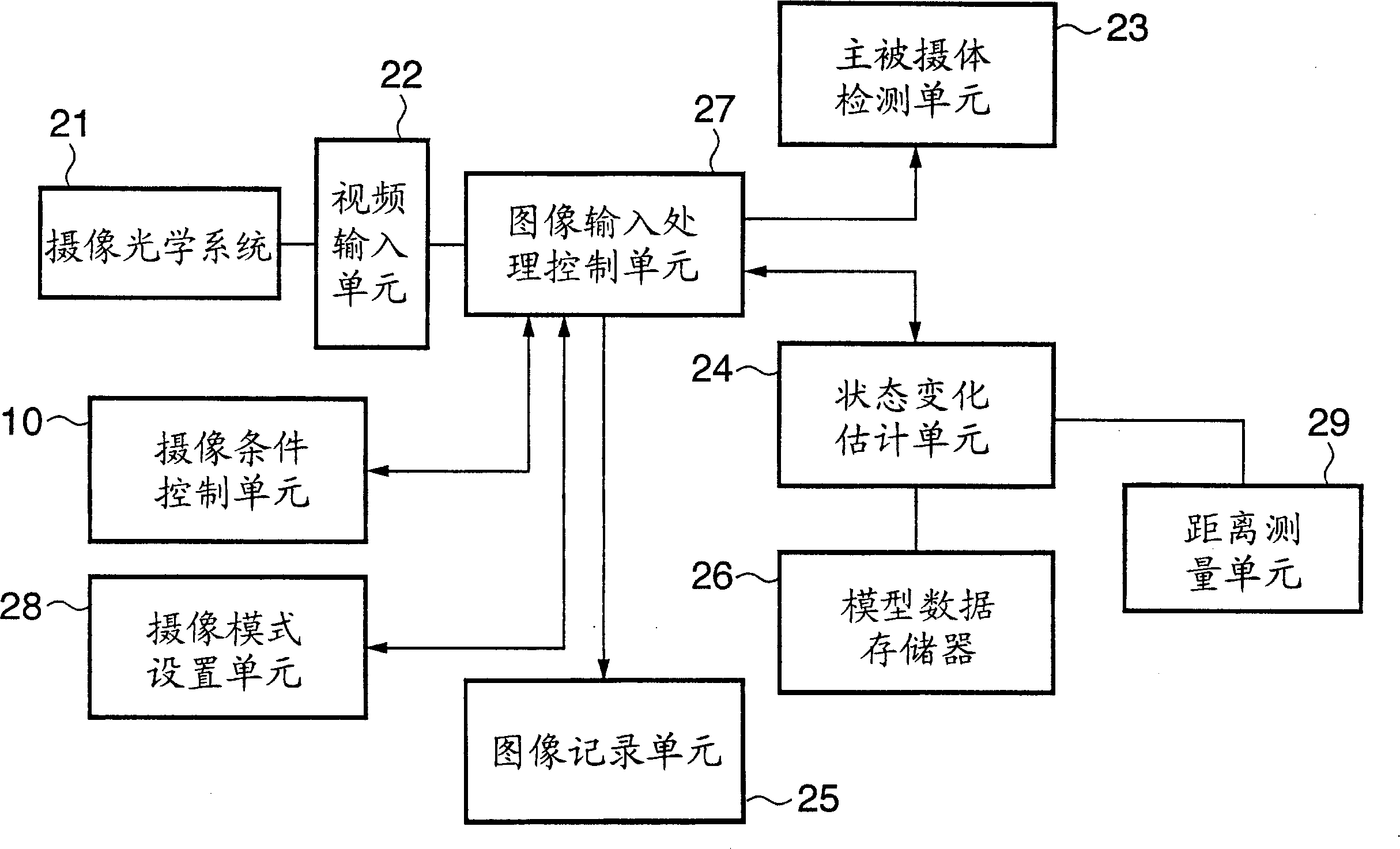
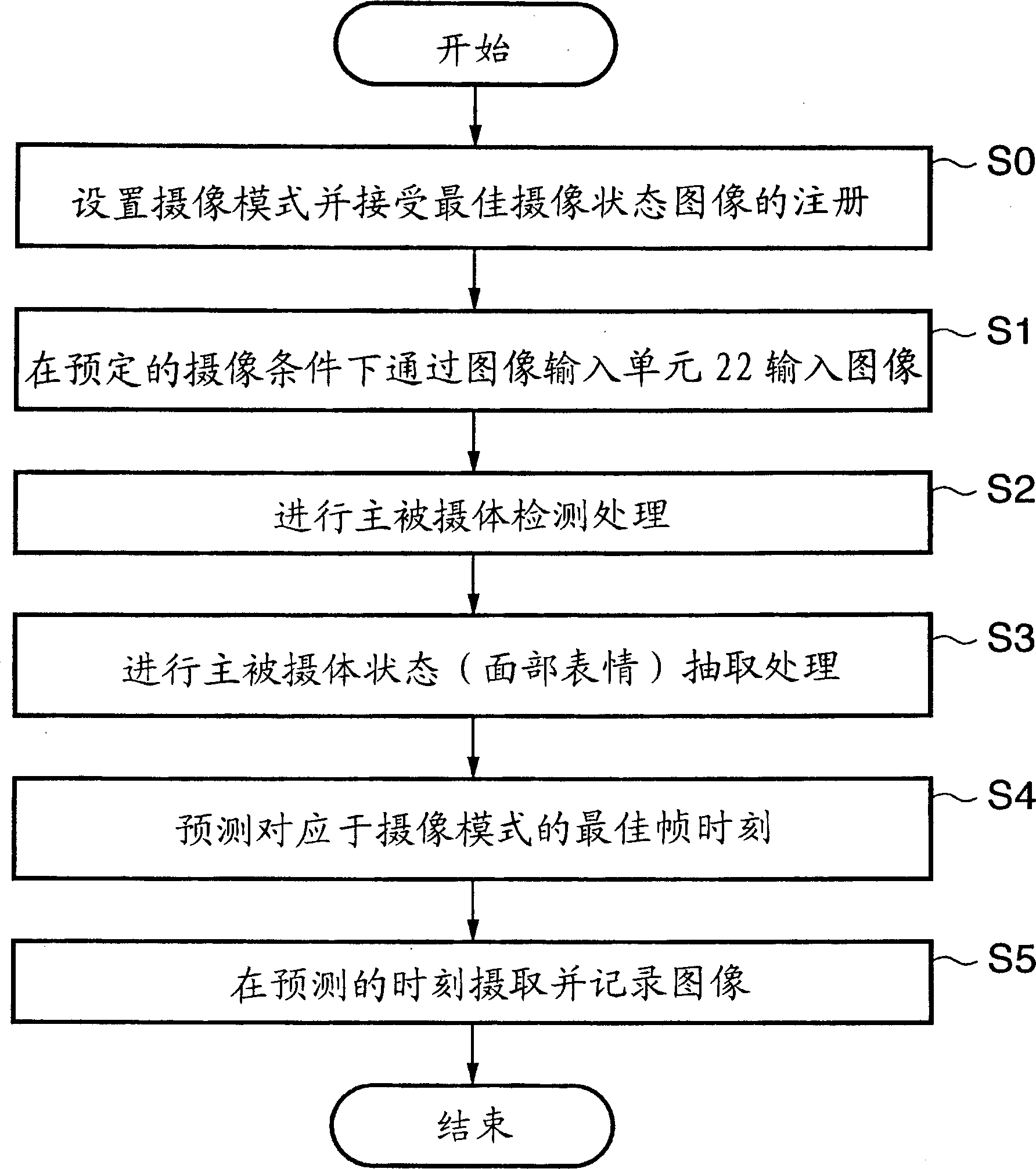
[0128] The first embodiment describes a structure in which the timing when the subject to be photographed satisfies a preset condition is estimated and image data corresponding to the predicted timing is stored and controlled. However, the estimation target is not limited to the imaging timing. The second embodiment will describe a structure in which shooting conditions such as exposure and focus at a timing suitable for shooting are estimated, and an image is captured under the shooting conditions.
[0129] figure 2 It is a block diagram showing the structure of the main part of the imaging apparatus according to the second embodiment. The structure according to the second embodiment includes in addition to the structure of the first embodiment: an imaging condition control unit 10 for controlling shooting conditions such as exposure and focus; and a distance measuring unit 29 for measuring the subject and imaging The distance between the devices. The remaining main structural ...
no. 3 example
[0150] In the third embodiment, in addition to the above structure, the imaging conditions are automatically controlled (changed) based on the result of detecting the motion pattern (content of the motion pattern) of the main subject (person).
[0151] Figure 6 It is a block diagram showing the structure of the main part of the imaging apparatus according to the third embodiment. Such as Figure 6 As shown, the imaging device according to the third embodiment includes: an imaging optical system 31, a video input unit 32, a main subject detection unit 33, a state change estimation unit 34, an image recording unit 35, a model data memory 36, and image input processing The control unit 37, the imaging mode setting unit 38, and the imaging condition control unit 300. These units and figure 1 Units 1 to 8 in and figure 2 The unit 10 in is the same, and a detailed description thereof is omitted.
[0152] In addition to the above-mentioned structure, the imaging apparatus according t...
PUM
 Abstract
Description
Claims
Application Information
 - R&D
- Intellectual Property
- Life Sciences
- Materials
- Tech Scout
- Unparalleled Data Quality
- Higher Quality Content
- 60% Fewer Hallucinations
Browse by: Latest US Patents, China's latest patents, Technical Efficacy Thesaurus, Application Domain, Technology Topic, Popular Technical Reports.
© 2025 PatSnap. All rights reserved.Legal|Privacy policy|Modern Slavery Act Transparency Statement|Sitemap|About US| Contact US: help@patsnap.com


