Oscillating piston engine

A technology of piston engine and rotary motion, which is applied in the direction of rotary piston engine, swing piston engine, swing piston engine, etc., and can solve problems such as incomplete elimination

Inactive Publication Date: 2007-02-07
赫伯特·许特林
View PDF2 Cites 3 Cited by
  • Summary
  • Abstract
  • Description
  • Claims
  • Application Information

AI Technical Summary

Problems solved by technology

In such a rotary piston engine, the working chamber and the pistons are also spherical wedge-shaped, wherein in this rotary piston engine the end faces of the pistons of a piston pair close to each other are concavely rounded on their sides close to the axis of rotation, whereby The above problems are mitigated, but not completely eliminated

Method used


Image

  • Oscillating piston engine
  • Oscillating piston engine
  • Oscillating piston engine

Examples


Embodiment Construction

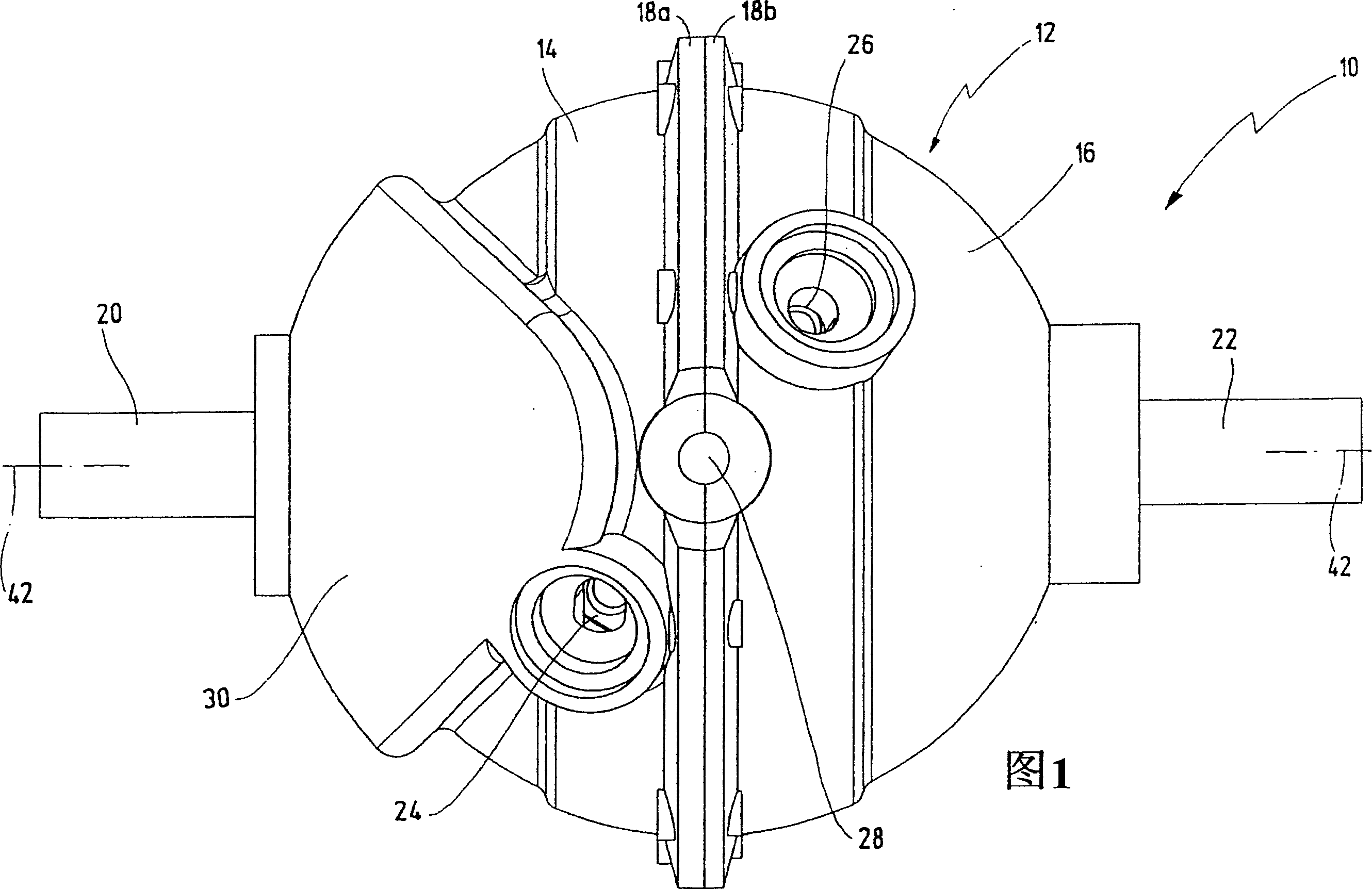
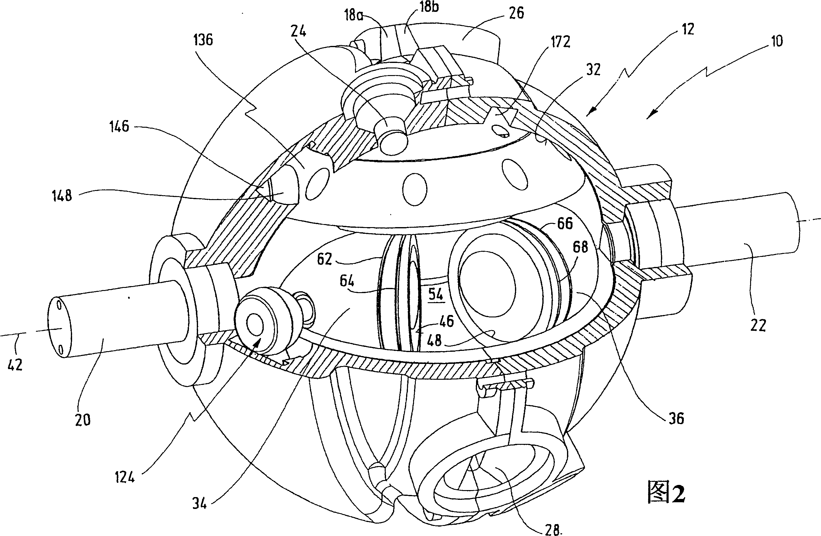
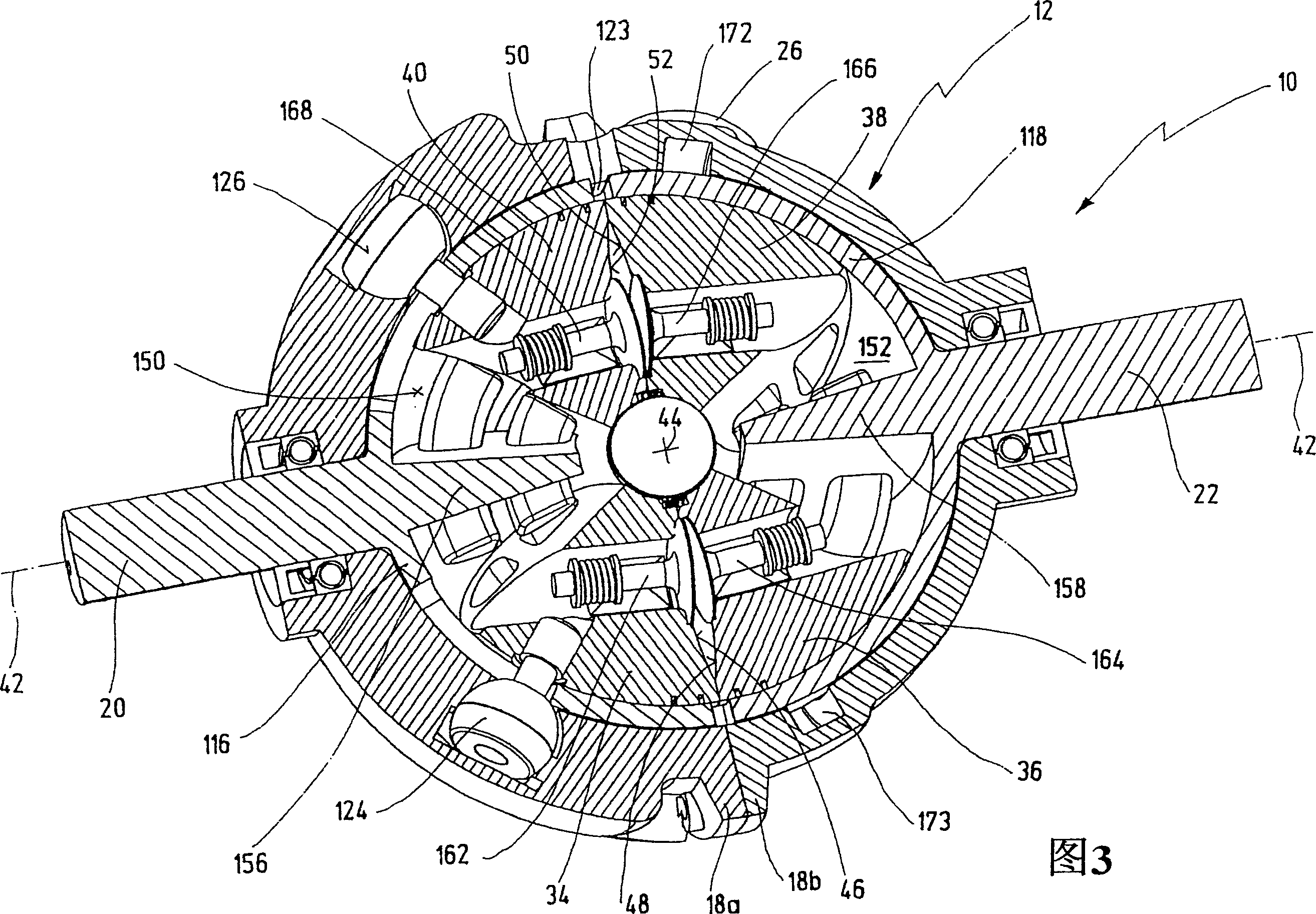
[0066] Figures 1-5, 8, 10 and 11 each show in general view a rotary piston engine having the common reference numeral 10. 6 and 7 and 9 and 12 show further details of the rotary piston engine 10 .

[0067] The rotary piston engine 10 is designed as an internal combustion engine in the present exemplary embodiment. However, in addition to the use of the rotary piston engine 10 as an internal combustion engine, it is also conceivable to slightly modify the rotary piston engine 10 for use as a compressor, a pump or the like.

[0068] The rotary piston engine 10 according to FIG. 1 has a substantially spherically symmetrical housing 12 . The housing 12 is composed of a housing part 14 and a housing part 16, which are releasably connected to one another via housing flanges 18a and 18b by screws.

[0069] The rotary piston engine 10 has a shaft 20 and a shaft 22 which protrude from the housing 12 on both sides. Instead of two shafts 20 and 22 it is also possible to have one shaft...


PUM


Abstract

An oscillating piston engine is described, having a housing (12) which has an at least approximately spherical inner wall (32), and having at least two pistons (34, 36) which can jointly revolve in the housing (12) about a fixed rotation axis (42) and, when revolving about the rotation axis (42), perform back-and-forth swivelling movements about at least one swivel axis (44) perpendicular to the rotation axis (42), wherein the swivelling movements of the two pistons (34, 36) are in opposition to one another, and wherein the two pistons (34, 36) each have an end face (46, 48), said end faces (46, 48) facing one another and each defining a front end of a working chamber (54) which is arranged completely outside the rotation axis (42) and is defined at the circumference by a working chamber wall (58). The working chamber (54), formed by the two end faces (46, 48) of the two pistons (34, 36) and the working chamber wall (58), and the pistons (34, 36) have the shape of a toroid section at least in the region of their ends facing the working chamber (54).

Description

technical field [0001] The invention relates to a rotary piston engine with a casing having an at least approximately spherical inner wall and at least two pistons co-rotatable inside the casing about a casing-fixed axis of rotation and During rotation, a reciprocating rotary motion is carried out about at least one rotary axis perpendicular to the rotary axis, wherein the rotary motions of the two pistons are oriented opposite to each other, wherein the two pistons each have an end face, which approach each other and each define a working chamber At the end-side end of , the working chamber is arranged completely outside the axis of rotation and is bounded in extent by the working chamber wall. Background technique [0002] Such a rotary piston engine is known from document WO 03 / 067033 A1. [0003] A rotary piston engine of this type can be used in particular as an internal combustion engine. In the case of a rotary piston engine used as an internal combustion engine, th...

Claims


Application Information

Patent Timeline
Patent Type & Authority Applications(China)
IPC IPC(8): F01C3/02F01C9/00
CPCF01C9/005
Inventor 赫伯特·许特林
Owner 赫伯特·许特林
Why Eureka
Try Eureka