
Single-way speed-reducing clutch

A one-way clutch and hollow shaft technology, applied in one-way clutches, clutches, machines/engines, etc., can solve problems such as high processing costs, inflexible expansion and contraction, waste of materials, and difficulty in processing

Inactive Publication Date: 2007-02-07
严绍康
View PDF0 Cites 11 Cited by
  • Summary
  • Abstract
  • Description
  • Claims
  • Application Information

AI Technical Summary

Problems solved by technology

[0002] With the development of society and the advancement of science and technology, the demand for internal combustion engines used in medium-sized and light vehicles, ships, generator sets and construction machinery is increasing day by day, and the demand for starter deceleration one-way clutches used in conjunction with internal combustion engines is also increasing; At present, most of the reduction-type one-way clutches produced in China are imitated with reference to foreign structures. Their structures are composed of gears, positioning sleeves, curved surfaces, positioning pins, hollow shafts, spline sleeves, large springs, etc. High, due to the limitation of its own production conditions, the product quality has not reached the foreign level. In the actual production and use process, there are the following deficiencies: First, due to the roughness, gear accuracy, radial runout of the pitch circle to the inner surface and the matching accuracy High requirements lead to waste of materials, difficulty in processing, and high processing costs; second, due to the complex structure and many parts, the processing procedures are complicated and the processing efficiency is low; the third is that the mechanical transmission is not stable during use, the radial runout is large, and the noise is large , it is easy to cause inflexible expansion and contraction, small transmission torque, and easy to slip; for this reason, many scientific research institutions, manufacturers and people of insight have conducted repeated research and tests, but so far there is no better improvement method

Method used


Image

  • Single-way speed-reducing clutch
  • Single-way speed-reducing clutch

Examples


Embodiment Construction

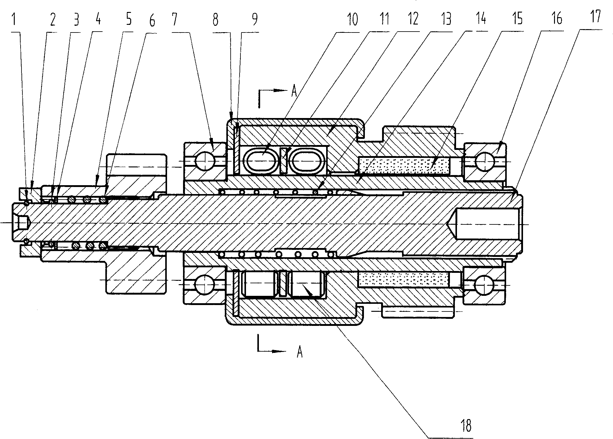
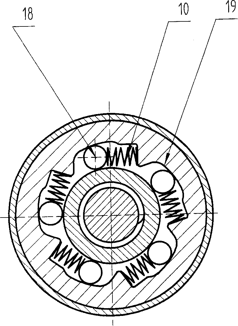
[0011] figure 1 and figure 2 Shown, for the present invention to create the specific embodiment of deceleration type one-way clutch, it comprises spline shaft 17, hollow shaft 14, large spring 13, hollow shaft 14 and large spring 13 are sleeved on the spline shaft 17, spline One end of the shaft 17 protrudes from the hollow shaft 14, and the other end is provided with an external helical spline and matched with the internal helical spline in the hollow shaft 14. The spline shaft 17 is provided with a spring stop ring, and the large spring 13 is used for reset and buffer Function, the hollow shaft 14 is provided with a gear flower sleeve 12 through the bushing 15, the outer ring at one end of the gear flower sleeve 12 is set as an outer gear, and the inner ring at the other end is provided with five raceway chambers 19, and in the raceway chamber The outer end surface of 19 is provided with a stop card 9 and a cover 8; the joint surface of the raceway chamber 19 and the rolle...


PUM


Abstract

The invention relates to a speed-reduction one-way clutch, which comprises: a spindle axle (17), a hollow axle (14), and a large spring (13), wherein the hollow axle (14) and the large spring (13) sheathes the spindle axle (17); one end of spindle axle (17) extrudes outside the hollow axle (14), while another end is arranged with external screw spindle axle to match the internal screw spindle of hollow axle (14); said hollow axle (14) via axle linear (15) is arranged with gear spindle sheath (12) whose outer ring at one end is the external gear while the inner ring at another end has five rolling rooms (19), and each room (19) has at least one group of rollers (18) and flat springs (10); the outer end of rolling room (19) is arranged with clamp plate (9) and cover (8). The invention has simple structure, low cost, low noise, large transmission torque and stable operation.

Description

technical field [0001] The invention relates to a one-way clutch, in particular to a starter reduction type one-way clutch for an internal combustion engine. Background technique [0002] With the development of society and the advancement of science and technology, the demand for internal combustion engines used in medium and light vehicles, ships, generator sets and construction machinery is increasing day by day, and the demand for starter deceleration one-way clutches used in conjunction with internal combustion engines is also increasing; At present, most of the deceleration one-way clutches produced in China are imitated with reference to foreign structures. Their structures are composed of gears, positioning sleeves, curved surfaces, positioning pins, hollow shafts, spline sleeves, and large springs. High, due to the limitation of its own production conditions, the product quality has not reached the foreign level. In the actual production and use...

Claims


Application Information

Patent Timeline
IPC IPC(8): F16D41/064F02N15/02
Inventor 严绍康
Owner 严绍康
Learn More