
Motor and motor manufacturing method

A manufacturing method and permanent magnet technology, applied in the manufacture of motor generators, stator/rotor bodies, electromechanical devices, etc., can solve problems such as unbalanced magnetization of permanent magnets

Inactive Publication Date: 2007-02-07
LG ELECTRONICS INC
View PDF0 Cites 5 Cited by
  • Summary
  • Abstract
  • Description
  • Claims
  • Application Information

AI Technical Summary

Problems solved by technology

[0009] The present invention is proposed to solve the above-mentioned problems, and mainly proposes a motor and a motor manufacturing method for improving the unbalanced magnetization of permanent magnets

Method used


Image

  • Motor and motor manufacturing method
  • Motor and motor manufacturing method
  • Motor and motor manufacturing method

Examples


Embodiment Construction

[0032] Reference will now be made in detail to the preferred embodiments of the present invention, examples of which are illustrated in the accompanying drawings. Wherever possible, the same reference numbers will be used throughout the drawings to refer to the same or like parts.

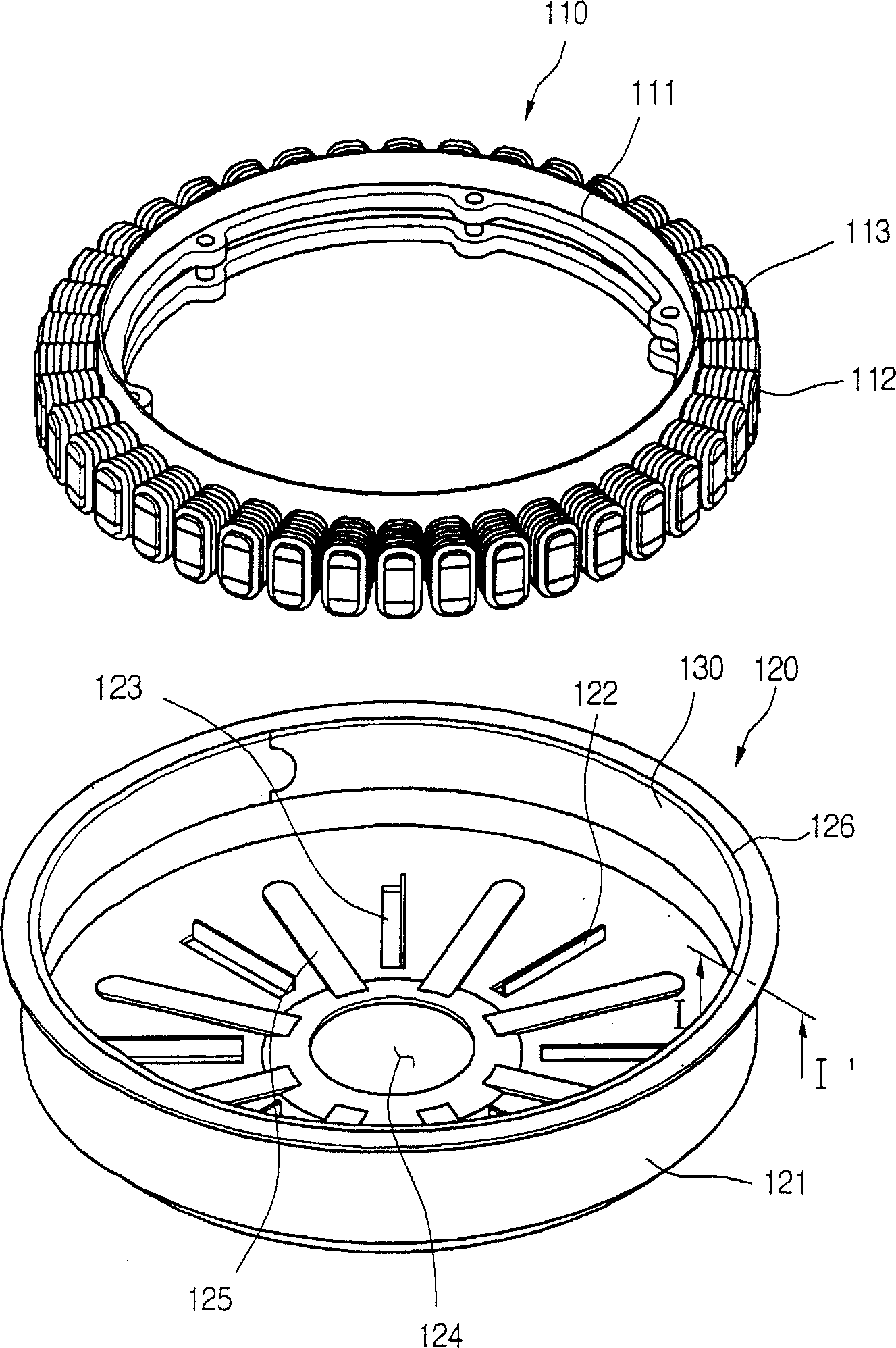
[0033] figure 1 is a perspective view of a disassembled motor according to the present invention.

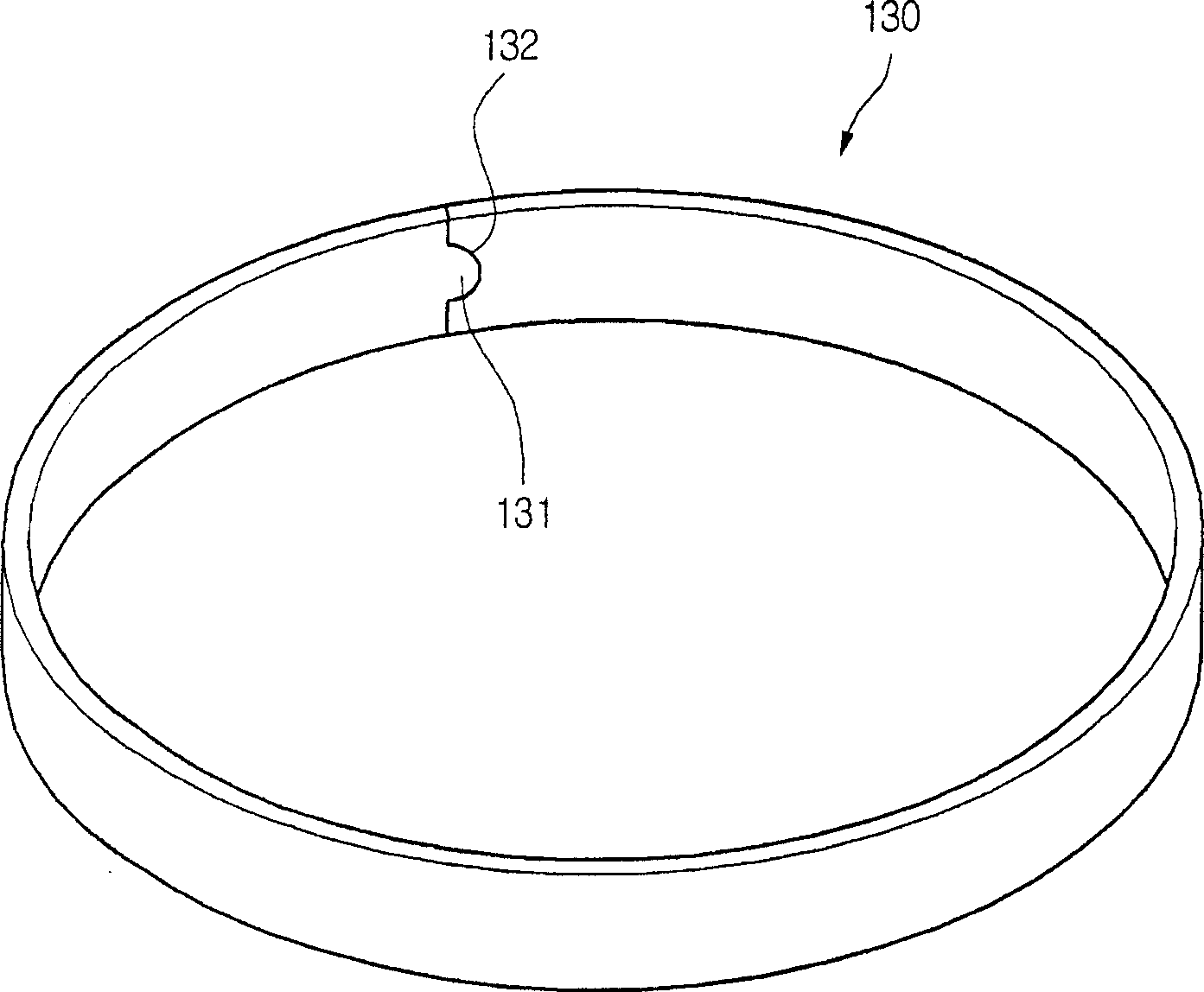
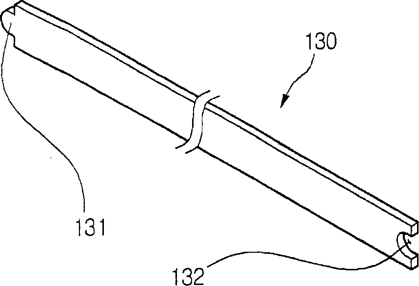
[0034] refer to figure 1 , The motor 100 according to the present invention includes: a stator 110 ; a rotor 120 rotating relative to the stator; and a permanent magnet 130 mounted to the rotor 120 .

[0035] In detail, the stator 110 is in a laminated form using magnets of approximately less than 1 mm. At this time, the number of laminations of magnets may be determined by the desired output of the motor 100 . The stator 110 includes a cylindrical yoke 111 and a plurality of winding portions 112 protruding from the yoke 111 .

[0036] More specifically, the winding portion 112 protrudes a prede...


PUM


Abstract

The motor of the present invention comprises: a stator, a rotor rotating to the stator and a permanent magnet installed to the rotor, wherein the permanent magnet is a single body and formed continuously.

Description

technical field [0001] The invention relates to a motor, in particular to an improved motor with unbalanced magnetization of permanent magnets and a manufacturing method of the motor. Background technique [0002] Generally, an electric motor is a device that drives other devices by converting electrical energy into mechanical energy. The motor includes: a stator, which is fixed to a specific device; a rotor, which rotates relative to the stator; and permanent magnets including sintered ferrite installed in the rotor. [0003] The permanent magnet also contains a fixed number of segments, and each segment is multipole-magnetized in radial direction. [0004] Since each segment in the electric machine is magnetized with multiple poles in the radial direction, an imbalance in the magnetization between the segments results. Higher frequencies are caused because of the unbalanced magnetization that occurs between the segments. High frequencies create current distortion and er...

Claims


Application Information

Patent Timeline
Patent Type & Authority Applications(China)
IPC IPC(8): H02K1/27H02K15/03
CPCH02K1/2786H02K1/28H02K1/32H02K9/06H02K15/03
Inventor 田且承闵丙旭全时汶
Owner LG ELECTRONICS INC
Learn More