Claw pole permanent magnet and electromagnetic hybrid excitation generator rotor production method

A technology of generator rotor and permanent magnet rotor, which is used in motors, manufacturing stator/rotor bodies, electric vehicles, etc., can solve the problems of low residual magnetic induction intensity, unstable output voltage, unadjustable magnetic field, etc., to ensure safety and reliability. Reliable use, stable output voltage, and high magnetic field utilization

Active Publication Date: 2015-09-16
张学义
View PDF5 Cites 0 Cited by
  • Summary
  • Abstract
  • Description
  • Claims
  • Application Information

AI Technical Summary

Problems solved by technology

[0002] At present, the production method of the permanent magnet generator rotor used in automobiles is to assemble the shaft and a full cylindrical permanent magnet, and then magnetize the cylindrical permanent magnet in a radial direction to form a permanent magnet with N poles and S poles arranged at intervals. Magnetic rotor, during the magnetization process, the magnetic molecules cannot be completely arranged in an orderly manner, the residual magnetic induction intensity is low, and because a part of the permanent magnetic material between the magnetic poles of the cylindrical permanent magnet does not work, the permanent magnetic material of the rotor with this structure The utilization rate is low, and because the permanent magnet magnetic field is a constant magnetic field, the magnetic field cannot be adjusted, the output voltage is low at low speed, the output voltage is high at high speed, and the output voltage is unstable, resulting in damage to the electrical equipment of the car or shortening the service life. Performance needs further improvement

Method used


Image

  • Claw pole permanent magnet and electromagnetic hybrid excitation generator rotor production method

Examples


Embodiment Construction

[0010] The present invention will be further described below in conjunction with accompanying drawing:

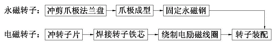
[0011] A method for producing a claw pole permanent magnet and electromagnetic hybrid excitation generator rotor, including permanent magnet rotor production, electric excitation rotor production, and rotor assembly, characterized in that:

[0012] The first step is the production of the permanent magnet rotor: the steel plate is punched and cut into claw-pole flanges, and then the claw-pole flanges are bent into claw poles, and the magnetic isolation bushing with positioning grooves is pressed on the On the shaft, the front claw poles are set on the magnetic isolation bushing with positioning grooves, the claws of the front claw poles face upward, and the axially magnetized circular permanent magnet steel is set on the magnetic isolation bushing, and then the rear The claw poles are set on the magnetic isolation bushing with positioning slots, the claws of the rear claw po...


PUM


Abstract

The invention provides a production method of rotors of a claw pole permanent magnet and electromagnet mixed excitation generator and belongs to the technical field of automotive electrical machines and electric appliances. The production method comprises permanent magnet rotor production, electro-magnetic rotor production and rotor assembly. The claw pole of a permanent magnet rotor converts an axial magnetization type magnetic field into a radial magnetic field, magnetic performance is good, and magnetization is uniform. An electro-magnetic rotor is of a salient pole structure, the magnetic field generated by the electro-magnetic rotor faces an air gap directly, leakage flux is low, and the utilizing rate of the magnetic field is high. The magnetic field in the air gap of the generator is provided by permanent magnet steel and electro-magnetic coils together, adjustment of the magnetic field formed after the permanent magnetic field and the electromagnetic field are combined is achieved by adjusting the intensity and direction of currents of the electro-magnetic coils, the output voltage of the generator is stable, and the safety and using reliability of the automotive electric appliances are guaranteed.

Description

technical field [0001] The invention provides a method for producing a claw pole permanent magnet and electromagnetic hybrid excitation generator rotor, which belongs to the technical field of automobile motors and electrical appliances. Background technique [0002] At present, the production method of the permanent magnet generator rotor used in automobiles is to assemble the shaft and a full cylindrical permanent magnet, and then magnetize the cylindrical permanent magnet in a radial direction to form a permanent magnet with N poles and S poles arranged at intervals. Magnetic rotor, during the magnetization process, the magnetic molecules cannot be completely arranged in an orderly manner, the residual magnetic induction intensity is low, and because a part of the permanent magnetic material between the magnetic poles of the cylindrical permanent magnet does not work, the permanent magnetic material of the rotor with this structure The utilization rate is low, and because...

Claims


Application Information

Patent Timeline
Patent Type & Authority Patents(China)
IPC IPC(8): H02K15/03
CPCY02T10/641Y02T10/64
Inventor 张学义杜钦君刘瑞军史立伟刘从臻尹红彬
Owner 张学义
Why Eureka
Try Eureka