Charge-pump type switching power supply apparatus

a power supply apparatus and charge-pump technology, applied in the direction of power conversion systems, dc-dc conversion, instruments, etc., can solve the problems of increasing the number of circuit components, obstructing the demand for reducing the size and cost of small information terminals, etc., to achieve the effect of reducing the size and cost of electronic devices and simplifying the structur

Active Publication Date: 2007-09-13
ROHM CO LTD
View PDF5 Cites 26 Cited by
  • Summary
  • Abstract
  • Description
  • Claims
  • Application Information

AI Technical Summary

Benefits of technology

[0029]According to this embodiment, the load circuits requiring a plurality of levels of drive voltages can be d...

Problems solved by technology

Thus, if this external flying capacitor is provided for each power supply apparatus, the number of circuit comp...

Method used


Image

  • Charge-pump type switching power supply apparatus
  • Charge-pump type switching power supply apparatus
  • Charge-pump type switching power supply apparatus

Examples


first embodiment

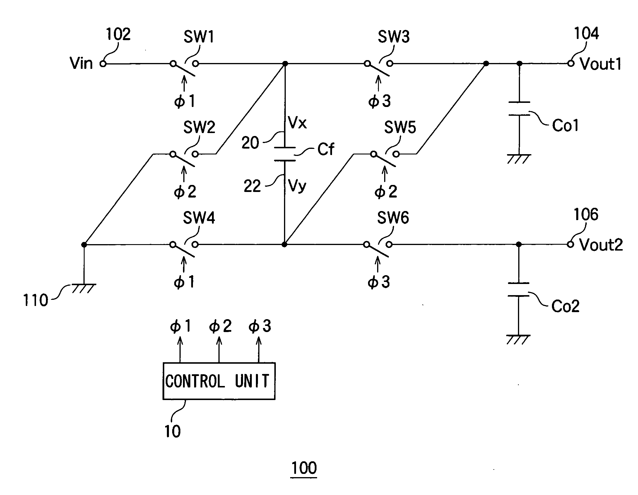
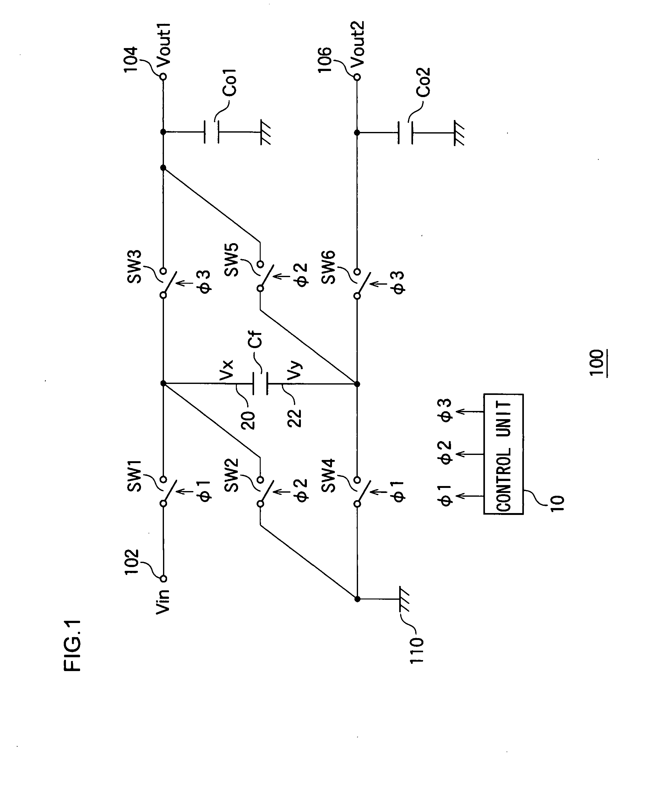
[0041]FIG. 1 is a circuit diagram showing a structure of a switching power supply apparatus 100 according to a first embodiment of the present invention. This switching power supply apparatus 100 includes an input terminal 102, a first output terminal 104, and a second output terminal 106. A first output voltage Vout1(=−Vin), having the reversed polarity of an input voltage Vin applied to the input terminal 102, is outputted from the first output terminal 104. A second output voltage Vout2(=−2×Vin), which is double the input voltage Vin with a reversed polarity, is outputted from the second output terminal 106.

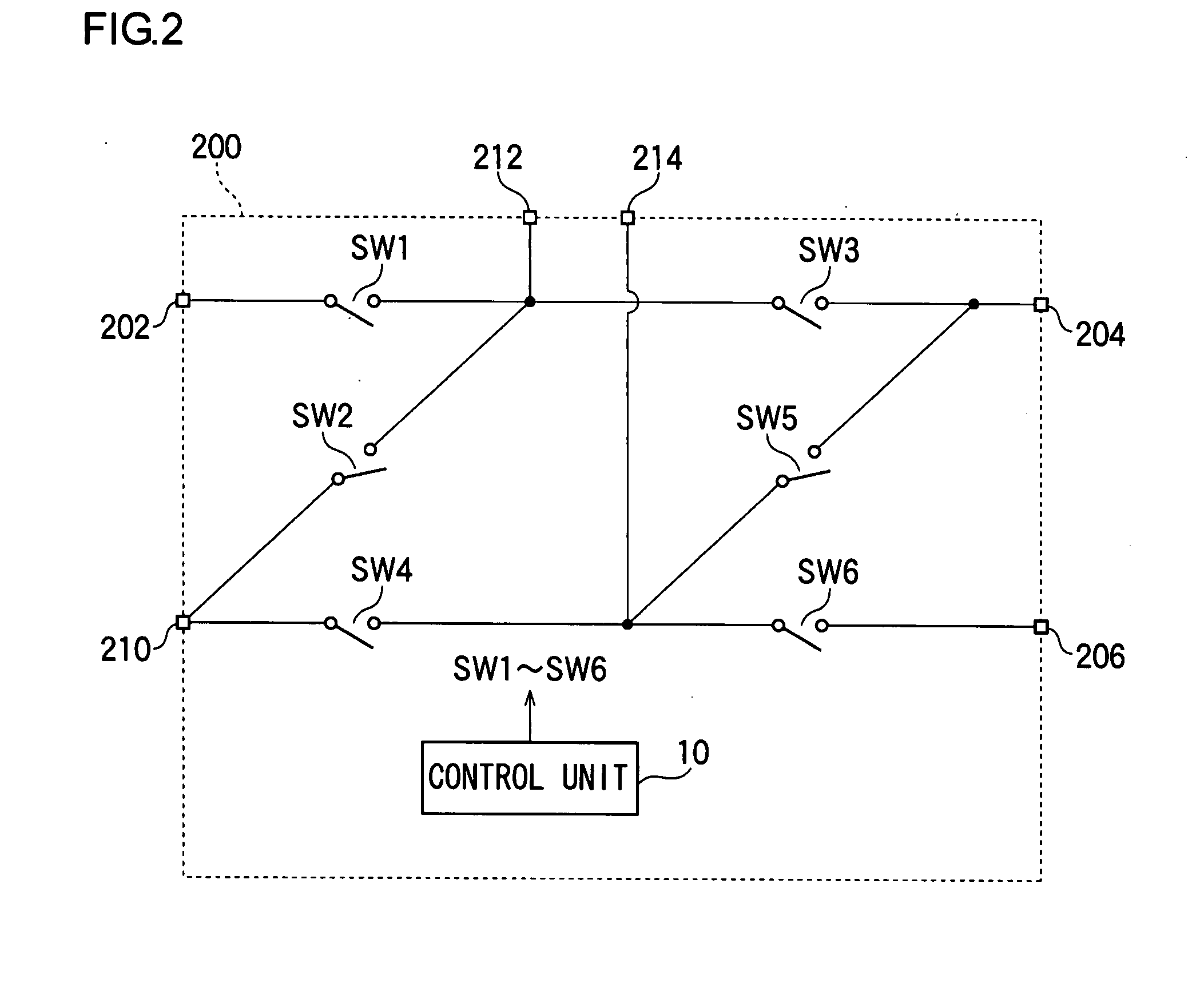
[0042]This switching power supply apparatus 100 is comprised of a flying capacitor Cf, a first switch SW1 to a sixth switch SW6, a first output capacitor Co1, a second output capacitor Co2, and a control unit 10 which controls the ON-OFF states of the first switch SW1 to the sixth switch SW6.

[0043]The first output capacitor Co1, which is provided between the first output termi...

second embodiment

[0075]A switching power supply apparatus according to a second embodiment of the present invention includes a function of outputting a third output voltage Vout3, in addition to the first output voltage Vout1 and the second output voltage Vout2 of the switching power supply apparatus 100 according to the first embodiment. The third output voltage Vout3 is double the input voltage Vin (=2×Vin).

[0076]FIG. 4 is a circuit diagram showing a structure of a switching power supply apparatus 100a according to a second embodiment of the present invention. For Figures shown hereinafter, the same or equivalent components as those described so far will be given the same reference numerals as before and the explanation thereof will be omitted as appropriate.

[0077]The switching power supply apparatus 100a includes a third output capacitor Co3, a seventh switch SW7 and an eighth switch SW8, in addition to the components of the switching power supply apparatus 100 shown in FIG. 1. In the second embo...


PUM


Abstract

A switching power supply apparatus generates a first output voltage with a reversed polarity of an input voltage and a second input voltage of double the input voltage with the reversed polarity, and then outputs them from the first output terminal and the second output terminal. A driver circuit includes a control unit and a first switch to a sixth switch. The driver circuit repeats three charging periods in a time-division manner. The three charging periods are a first charging period during which a flying capacitor is charged with the input voltage, a second charging period in which a low-potential-side terminal of the flying capacitor is connected to a ground terminal and a first output capacitor is charged with a voltage appearing at the other end of the flying capacitor, and a third charging period in which a high-potential-side of the flying capacitor is connected with the first output terminal and a second output capacitor is charged with a voltage appearing at the other end of the flying capacitor.

Description

BACKGROUND OF THE INVENTION[0001]1. Field of the Invention[0002]The present invention relates to a charge-pump type switching power supply apparatus.[0003]2. Description of the Related Art[0004]For the compact-size information terminals in recent years such as mobile phones and PDAs (Personal Digital Assistance), there are some devices such as LEDs (Light Emitting Diode) used for the backlight of a liquid display, for instance, wherein they require a voltage higher than the output voltage of a battery. For example, Li-ion batteries are often used for these small-size information terminals. The output voltage thereof is normally about 3.5 V, and when fully charged, it is about 4.2 V. However, as the LED driving voltage, the LED requires voltage higher than the battery voltage. Accordingly, when the voltage higher than the battery voltage is required, a booster circuit of a switched-capacitor or the like method is used to boost the battery voltage so as to obtain the voltage necessary...

Claims


Application Information

Patent Timeline
IPC IPC(8): H02M3/06
CPCH02M3/07
Inventor OYAMA, MANABUUCHIMOTO, DAISUKE
Owner ROHM CO LTD
Why Eureka
Try Eureka