Layered solid-state battery

a solid-state battery and layered technology, applied in the direction of cell components, final product manufacturing, sustainable manufacturing/processing, etc., can solve the problem of leakage of electrolytic solution, and achieve the effect of stable output voltag

Active Publication Date: 2013-06-13
MURATA MFG CO LTD
View PDF5 Cites 27 Cited by
  • Summary
  • Abstract
  • Description
  • Claims
  • Application Information

AI Technical Summary

Benefits of technology

[0029]As described above, according to the present invention, the same pole is disposed on both sides of the internal collection layer, so that a monopolar layered solid-state battery in which a plurality of unit cells are connected in parallel with an internal collection layer intervening therebetween can be obtained. Also, with a simple construction, the plurality of unit cells constituting the layered solid-state battery can be connected in parallel, and the positive electrode layers or the negative electrode layers can be ion-conductively conducted with each other in adjacent two unit cells, so that the electric potential between the positive electrode layers or the negative electrode layers that are adjacent to each other with the internal collection layer intervening therebetween can be leveled, and a stable output voltage can be obtained.

Problems solved by technology

However, in a secondary battery using an electrolytic solution, there is a problem such as leakage of the electrolytic solution.

Method used


Image

  • Layered solid-state battery
  • Layered solid-state battery
  • Layered solid-state battery

Examples


first embodiment

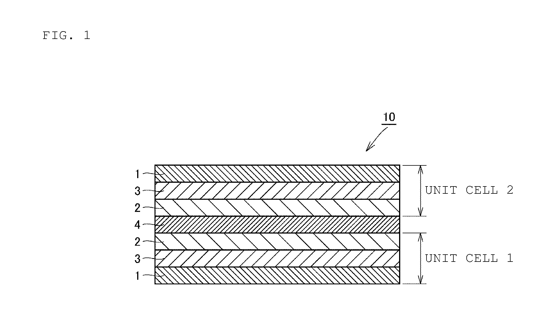
[0038]First, a layered body that forms a basic structure of a layered solid-state battery will be described as a first embodiment of the present invention. Here, in each of the later-described embodiments of the present invention, the planar shape of the layered body is not limited; however, description will be given assuming that the shape is generally a rectangular shape.

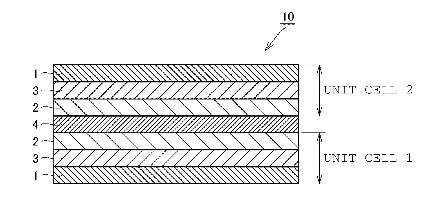
[0039]As illustrated in FIG. 1, in a layered solid-state battery 10, a (unit cell 1) and a (unit cell 2) are stacked with an internal collection layer 4 intervening therebetween. Each of the (unit cell 1) and the (unit cell 2) is constituted of a positive electrode layer 1, a solid electrolyte layer 3, and a negative electrode layer 2 that are sequentially stacked.

[0040]The (unit cell 1), the (unit cell 2), and the internal collection layer 4 are stacked so that the negative electrode layer 2 of the (unit cell 2) is adjacent to one side surface (the upper surface in FIG. 1) of the internal collection layer 4, and ...

second embodiment

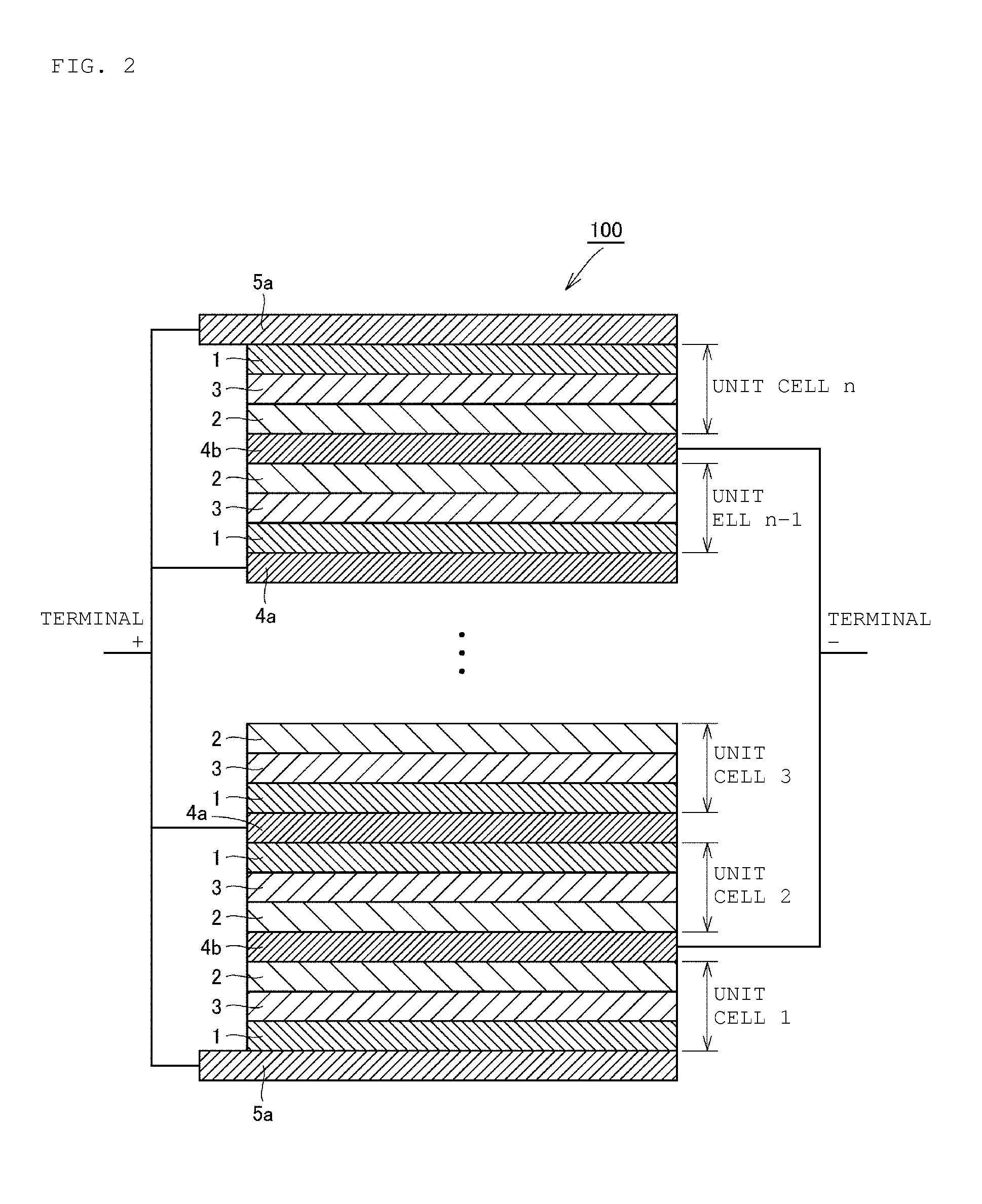
[0060]Next, as a second embodiment of the present invention, a layered solid-state battery having a layered solid-state battery 10 illustrated in FIG. 1 as a basic structure will be described. FIG. 2 is a cross-sectional view schematically illustrating a cross-sectional structure of a layered solid-state battery in the case where an even number of unit cells are provided, and FIG. 3 is a cross-sectional view schematically illustrating a cross-sectional structure of a layered solid-state battery in the case where an odd number of unit cells are provided.

[0061]As illustrated in FIG. 2, in the same manner as in FIG. 1, in a layered solid-state battery 100, n pieces (an even number) of (unit cells 1 to n) are stacked with internal collection layers 4a, 4b intervening therebetween. As illustrated in FIG. 3, in the same manner as in FIG. 1, in a layered solid-state battery 200, n+1 pieces (an odd number) of unit cells are stacked with internal collection layers 4a, 4b intervening therebet...

examples

[0070]Hereafter, Examples of the present invention will be described.

[0071]An Example in which a layered solid-state battery according to the second embodiment of the present invention was actually fabricated will be described.

[0072]

[0073]Active substance powder including a lithium-containing vanadium phosphoric acid compound (Li3V2(PO4)3) (hereafter referred to as LVP) as an active substance material and carbon powder as an electrically conductive agent was synthesized by the following procedure.

[0074](1) The powders of Li2CO3, V2O5, and (NH4)2H(PO4)3 as raw materials were mixed in a mortar so as to attain a stoichiometric ratio of LVP.

[0075](2) The obtained mixed powder was fired at a temperature of 600° C. for 10 hours in an air atmosphere.

[0076](3) To the obtained fired powder, carbon powder as an electrically conductive material was added and mixed in a mortar.

[0077](4) The obtained mixed powder was fired at a temperature of 950° C. for 10 hours in an argon gas atmosphere.

[0078...


PUM

PropertyMeasurementUnit
temperatureaaaaaaaaaa
thicknessaaaaaaaaaa

Abstract

A layered solid-state battery that includes a first unit cell, a second unit cell, and an internal collection layer that is disposed to intervene between the first unit cell and the second unit cell. Each of the unit cells is constituted of a positive electrode layer, a solid electrolyte layer, and a negative electrode layer that are sequentially stacked. The internal collection layer is disposed to be in contact with each of the negative electrode layers of the unit cells. Also, the internal collection layer contains an electron conductive material and an ion-conductively electrically conductive specific conductive material.

Description

CROSS REFERENCE TO RELATED APPLICATIONS[0001]The present application is a continuation of International application No. PCT / JP2011 / 067925, filed Aug. 5, 2011, which claims priority to Japanese Patent Application No. 2010-178500, filed Aug. 9, 2010, the entire contents of each of which are incorporated herein by reference.FIELD OF THE INVENTION[0002]The present invention generally relates to a layered solid-state battery, and specifically to a layered solid-state battery constructed so that unit cells are connected in parallel.BACKGROUND OF THE INVENTION[0003]In recent years, as a power supply of portable electronic equipment such as a portable phone or a portable personal computer, a battery, in particular a secondary battery, is used. As one example of a secondary battery, a lithium ion secondary battery is known to have a relatively large energy density. In such a secondary battery, a liquid electrolyte (electrolytic solution) of an organic solvent or the like is conventionally us...

Claims


Application Information

Patent Timeline
Patent Type & Authority Applications(United States)
IPC IPC(8): H01M2/20H01M50/512H01M50/528
CPCH01M4/66H01M10/044Y02E60/122H01M10/0585H01M2/204H01M10/052Y02E60/10Y02P70/50H01M50/512
Inventor HAYASHI, TAKESHIOUCHI, MASUTAKANISHIDA, KUNIOYOSHIOKA, MAKOTO
Owner MURATA MFG CO LTD
Why Eureka
Try Eureka