Power supply device and operations control method thereof

a power supply device and operation control technology, applied in the direction of automatic control, process and machine control, instruments, etc., can solve the problems of lowering overall conversion efficiency and difficulty in providing steady voltage, and achieve steady output voltage and high efficiency

Inactive Publication Date: 2010-04-20
RICOH ELECTRONIC DEVICES CO LTD
View PDF11 Cites 25 Cited by
  • Summary
  • Abstract
  • Description
  • Claims
  • Application Information

AI Technical Summary

Benefits of technology

[0007]In an aspect of this disclosure, there is provided a power supply device equipped with an LDO and a switching regulator in parallel and used by switching between the LDO and the switching regulator depending on a current load situation, thereby making it possible to achieve overall high efficiency and supply a steady output voltage even at the switching; and an operations control method thereof.
[0008]According to another aspect, there is provided a power supply device that outputs an input voltage input to an input terminal from a predetermined output terminal as an output voltage after converting it into a predetermined voltage. The device comprises a synchronous rectification switching regulator that outputs the input voltage to the output terminal after converting it into a predetermined voltage; a linear regulator that outputs the input voltage to the output terminal after converting it into a predetermined voltage; and a timing adjustment circuit unit that controls driving of the linear regulator and the synchronous rectification switching regulator in accordance with a control signal input from outside. The synchronous rectification switching regulator is controlled to be driven by the control signal from the outside and reduces current drive performance of a synchronous rectification transistor that discharges an inductor charged with the input voltage by a switching operation of a switching transistor until a predetermined signal has been input from the timing adjustment circuit unit after being started with the control signal from the outside.
[0010]Further, the timing adjustment circuit unit outputs the predetermined signal to the synchronous rectification switching regulator to reduce the current drive performance of the synchronous rectification transistor until a second predetermined time longer than the first predetermined time has elapsed after the synchronous rectification switching regulator is started.
[0011]Specifically, the synchronous rectification switching regulator comprises a switching transistor that performs switching operations in accordance with a first input control signal; the inductor charged with the input voltage by the switching operation of the switching transistor; a first synchronous rectification transistor that performs switching operations in accordance with a second input control signal to discharge the inductor; a second synchronous rectification transistor having current drive performance lower than that of the first synchronous rectification transistor and performing switching operations in accordance with a third input control signal to discharge the inductor; a control circuit unit that performs switching control with respect to the switching transistor so that the output voltage output from the output terminal becomes the predetermined voltage while causing the first and / or second synchronous rectification transistor(s) to perform switching operations contrary to the switching transistor. The control circuit unit turns off the first synchronous rectification transistor to cut off an electrical connection while using the second synchronous rectification transistor to discharge the inductor during the signal for reducing the current drive performance of the synchronous rectification transistor being input from the timing adjustment circuit unit.
[0016]According to still another aspect, there is provided an operations control method of a power supply device that comprises a synchronous rectification switching regulator and a linear regulator that outputs an input voltage input to an input terminal from a predetermined output terminal as an output voltage after converting it into a predetermined voltage and switches and actuates either of the synchronous rectification switching regulator or the linear regulator in accordance with a control signal from outside. The method comprises actuating the linear regulator during a first predetermined time and reducing current drive performance of a synchronous rectification transistor in the synchronous rectification switching regulator until a second predetermined time longer than the first predetermined time has elapsed when the control signal from the outside indicating the switch from the linear regulator to the synchronous rectification switching regulator is input.
[0020]According to preferred embodiments of the above-mentioned power supply device and operations control method, the linear regulator is actuated during the first predetermined time, and the current drive performance of the synchronous rectification transistor in the synchronous rectification switching regulator is reduced until the second predetermined time longer than the first predetermined time has elapsed when the control signal from the outside indicating the switch from the linear regulator to the synchronous rectification switching regulator is input. Accordingly, it is possible to achieve low current consumption by the use of the linear regulator with low current consumption at light load and achieve high efficiency by the use of the switching regulator at heavy load. In addition, it is possible to reduce the undershoot in the output voltage which could occur right after the switching regulator is started and supply a steady output voltage.

Problems solved by technology

In this case, high power conversion efficiency can be obtained at heavy load, but current consumption of the switching regulator itself is increased at light load, resulting in lowering overall conversion efficiency.
Furthermore, since an overshoot or an undershoot occurs in an output voltage when an LDO and a switching regulator are switched with each other, there is a necessity to reduce the overshoot and the undershoot in the output voltage occurring at the switching in consideration of the method and the timing of switching between the LDO and the switching regulator.
As a result, the drop of an output voltage or the like occurs, thereby making it difficult to supply a steady voltage.

Method used


Image

  • Power supply device and operations control method thereof
  • Power supply device and operations control method thereof
  • Power supply device and operations control method thereof

Examples


first embodiment

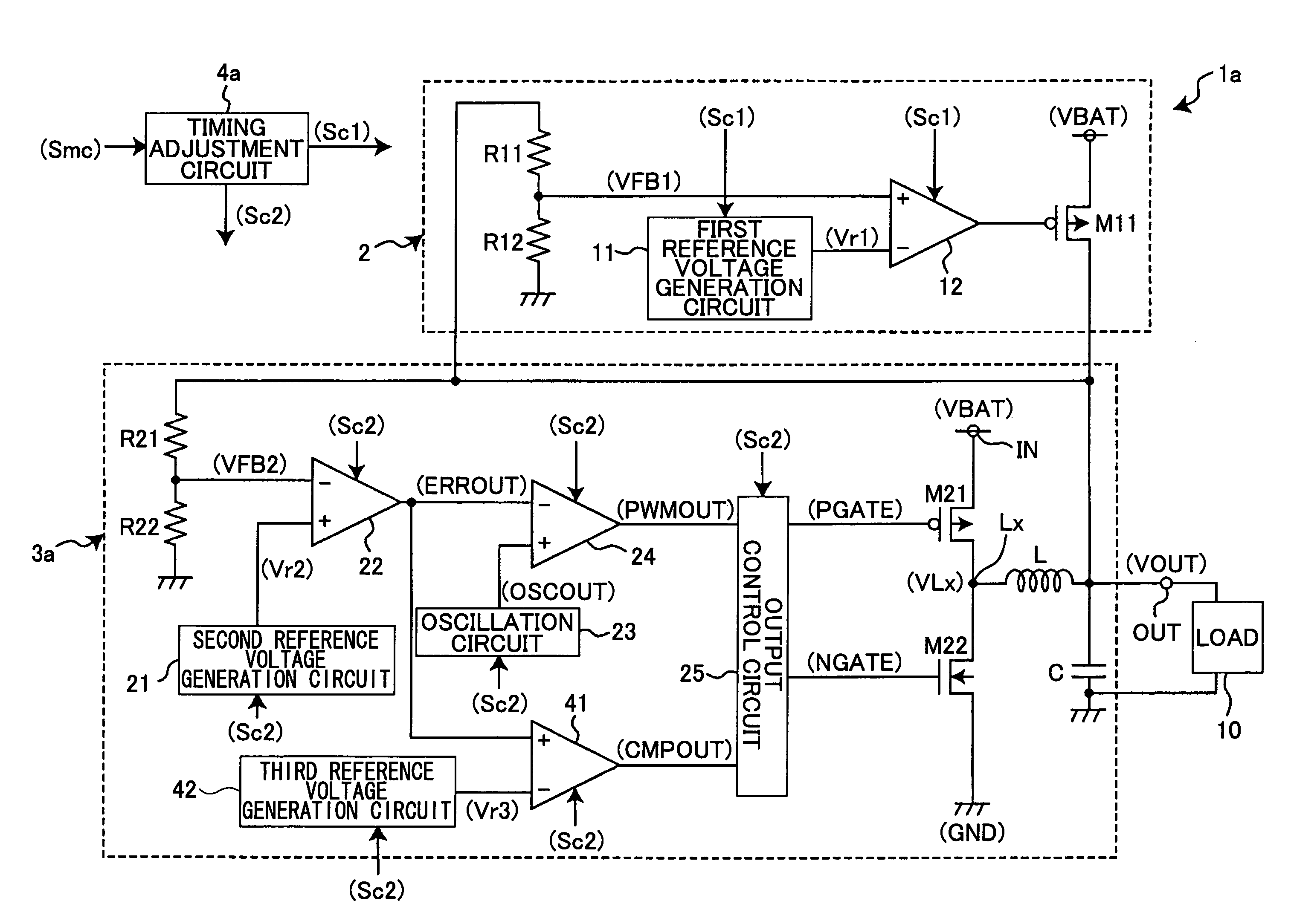
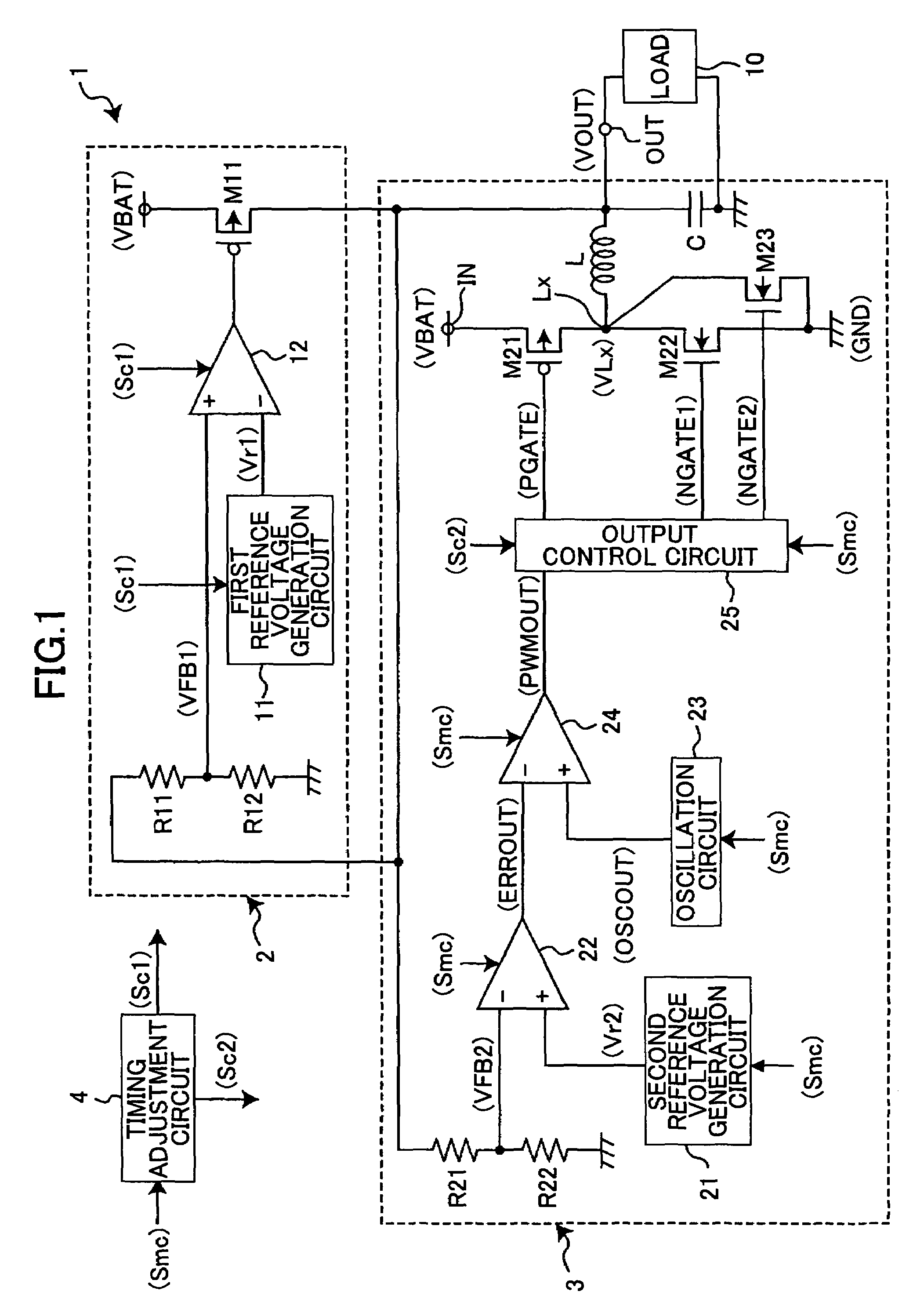
[0027]FIG. 1 is a diagram showing a circuit example of a power supply device of a first embodiment of the present invention.

[0028]In FIG. 1, the power supply device 1 converts an input voltage VBAT input to an input terminal IN into a predetermined constant voltage V1 and outputs the converted voltage to a load 10 from an output terminal OUT as an output voltage VOUT.

[0029]The power supply device 1 is composed of a LDO 2 serving as a linear regulator, a switching regulator 3 serving as a DC-DC converter, and a timing adjustment circuit 4 that controls driving of the LDO 2 and switching regulator 3 in accordance with a switching signal Smc input from the outside. The switching signal Smc is input so as to actuate the LDO 2 in a low current consumption operation mode such as a sleep mode and actuate the switching regulator 3 in a normal operation mode. The output terminals of the LDO 2 and the switching regulator 3 and their input terminals are connected to the output terminal OUT of ...

second embodiment

[0048]In the above first embodiment, the synchronous rectification transistor having the low current drive performance is used until the second predetermined time T2 has elapsed after the switching regulator 3 is started. Alternatively, both of the switching transistor and the synchronous rectification transistor may be turned off to cut off an electrical connection until the output voltage of the error amplification circuit 22 becomes equal to or greater than a predetermined value at the starting of the switching regulator 3. A description is now made of this modification as a second embodiment.

[0049]FIG. 3 is a diagram showing a circuit example of the power supply device according to the second embodiment of the present invention. In FIG. 3, components the same as or similar to those of FIG. 1 are indicated by the same numerals and are not be described below. Here, only parts different from FIG. 1 are described.

[0050]FIG. 3 is different from FIG. 1 in that the synchronous rectific...


PUM


Abstract

A LDO and a switching regulator are connected in parallel with each other. The power supply device selects and actuates either of the LDO or the switching regulator in accordance with a switching signal from the outside. When making the switch from the LDO to the switching regulator so as to be actuated, the power supply device causes operation periods of the LDO and the switching regulator to overlap each other. At least during the period in which the operation periods overlap each other, the power supply device makes current drive performance of a synchronous rectification transistor of the switching regulator lower and makes the same return to a normal state after the LDO stops its operation.

Description

BACKGROUND OF THE INVENTION[0001]1. Field of the Invention[0002]This disclosure relates to a power supply device that switches and outputs either of the output voltage of a LDO (Low Dropout) converter (hereinafter referred to as LDO) serving as a linear regulator or that of a switching regulator, depending on a load current so as to lower current consumption at light load, thereby making it possible to reduce overall power consumption, and to an operations control method thereof.[0003]2. Description of the Related Art[0004]As a known method for outputting an input voltage after converting it into a predetermined voltage in a power supply device, there has widely been employed one that converts power with high conversion efficiency by the use of a switching regulator. In this case, high power conversion efficiency can be obtained at heavy load, but current consumption of the switching regulator itself is increased at light load, resulting in lowering overall conversion efficiency. Th...

Claims


Application Information

Patent Timeline
Patent Type & Authority Patents(United States)
IPC IPC(8): G05F1/59G05F1/575
CPCG05F1/575G05F1/56H02M3/155
Inventor INOUE, YOSHIYUKI
Owner RICOH ELECTRONIC DEVICES CO LTD
Why Eureka
Try Eureka