Turning hinge mechanism and image pick up device

A hinge mechanism, a technology of a camera device, applied in the camera, image communication, camera body and other directions

Inactive Publication Date: 2007-02-07
SONY CORP
View PDF2 Cites 2 Cited by
  • Summary
  • Abstract
  • Description
  • Claims
  • Application Information

AI Technical Summary

Problems solved by technology

Such a friction mechanism not only leads to an increase in the size of the imaging device, but a...

Method used


Image

  • Turning hinge mechanism and image pick up device
  • Turning hinge mechanism and image pick up device
  • Turning hinge mechanism and image pick up device

Examples


Embodiment Construction

[0039] Hereinafter, the swing hinge mechanism and the imaging device to which the present invention is applied will be described in detail with reference to the accompanying drawings.

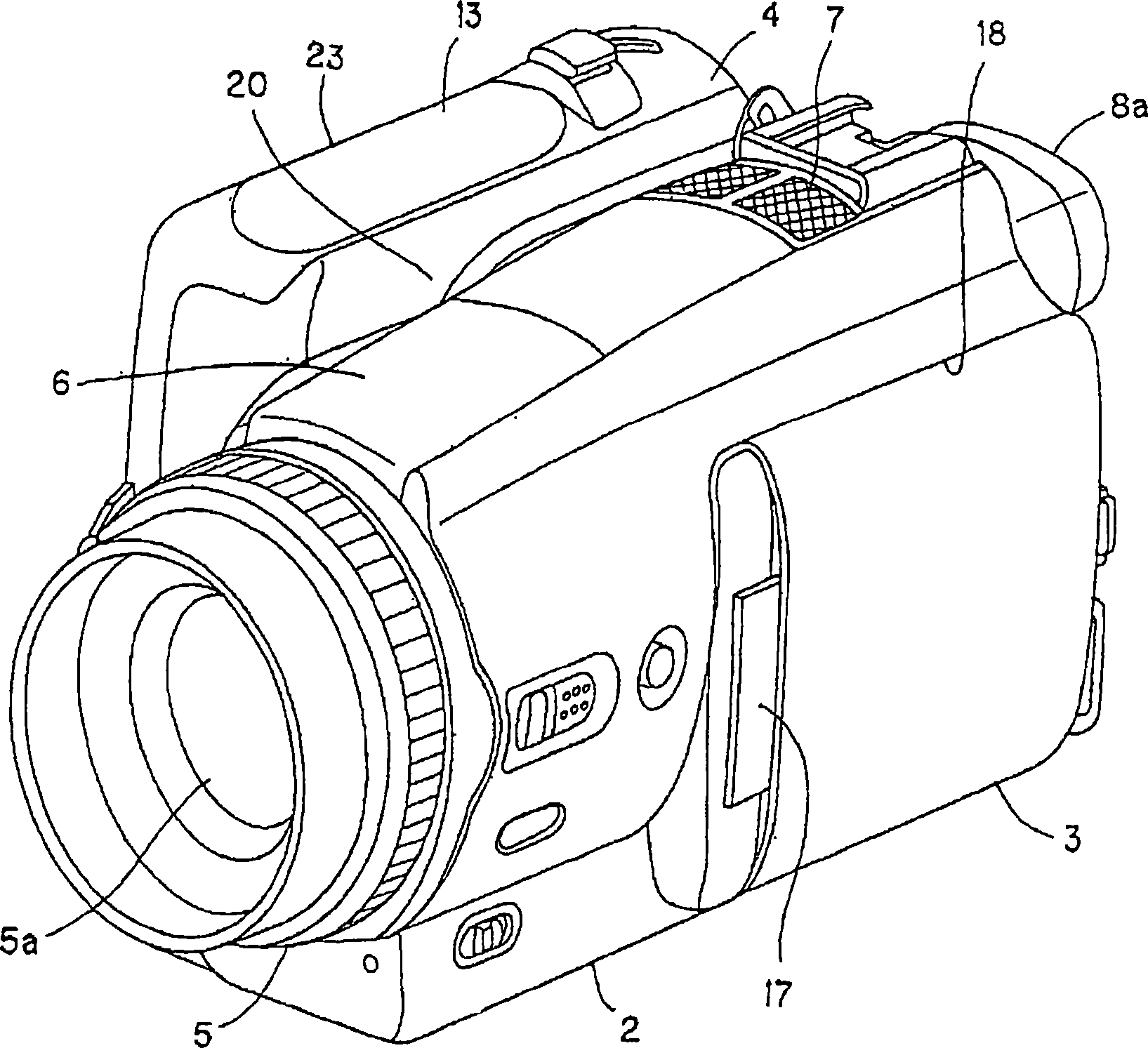
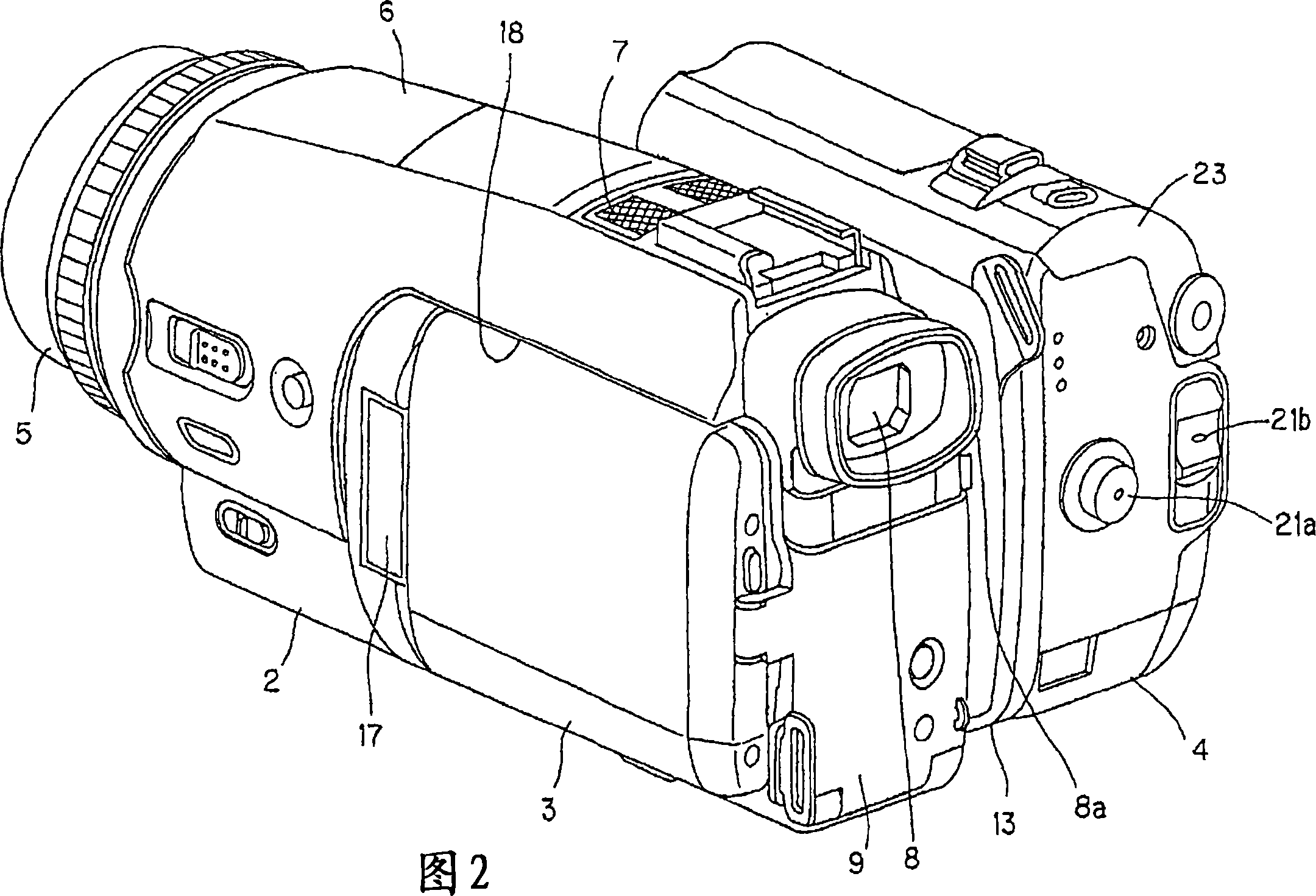
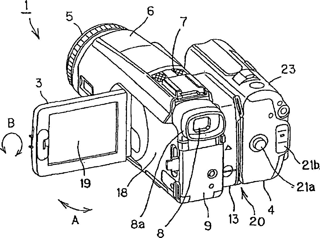
[0040] The imaging device to which the present invention is applied is, for example, shown in figure 1 And the camera-integrated digital video tape recorder (hereinafter referred to as a digital video camera) 1 of FIG. 2. The digital camera 1 has a main body 2, a panel part (パネル part) 3 that is openably and closably attached to one side of the main body 2, and another one that is rotatably attached to the main body 2 on the opposite side of the panel 3 The side handle part 4.

[0041] The main body portion 2 has an imaging unit for photographing an image of a subject, and a lens portion 5 for extending the imaging lens 5a to the outside is protrudingly provided in front of the main body portion 2. In addition, on the upper surface of the main body 2, a strobe light emitting section 6 that emits a ...


PUM


Abstract

A turning hinge mechanism for turnable support between a video camera main body part (2) and a grip part (4). The mechanism is provided with a fixing board (31) mounted on either of the main body part or the grip part, and rotating boards (32) and (33) mounted on the other of the main body part and the grip part, and a spindle (34) for turnably supporting these rotating boards on the fixing board. On the fixing board and each rotating board, first and second opening parts (40) and (54) are formed to penetrate a harness (66) which turns between the main body part and the grip part. The first and the second opening parts are formed to overlap at least partly within an angle range at which the grip part turns around the main body part.

Description

Technical field [0001] The present invention relates to a rotary hinge mechanism that rotatably supports between a main body and a rotary part, and an imaging device in which a handle part is rotatably mounted relative to the main body by such a rotary hinge mechanism. [0002] This application claims priority on the basis of Japanese Patent Application No. 2004-016276 and Japanese Patent Application No. 2004-016279 filed in Japan on January 23, 2004, and this application is incorporated into this application by reference. Background technique [0003] In imaging devices such as digital still cameras and digital video cameras, all functions can be integrated into the main body of the device to reduce the overall size of the device. In the imaging device, the device itself is held during shooting. Therefore, it is difficult to hold certain shapes of the device. For certain postures and angles during shooting, it is difficult to shoot at a stable angle. [0004] Therefore, in the i...

Claims


Application Information

Patent Timeline
IPC IPC(8): H04N5/225G03B17/02G03B17/56
Inventor 五十岚锐
Owner SONY CORP
Why Eureka
Try Eureka