Method for open-end rotor spinning

A technology of air spinning and spinning cup, which is applied in the direction of spinning machine, open end spinning machine, continuous winding spinning machine, etc. It can solve the problem of damage to yarn structure or fiber orientation and fiber draft, and limit air spinning Yarn application range and other issues

Inactive Publication Date: 2006-10-18
OERLIKON TEXTILE GMBH & CO KG
View PDF4 Cites 0 Cited by
  • Summary
  • Abstract
  • Description
  • Claims
  • Application Information

AI Technical Summary

Problems solved by technology

This impairs the yarn structure or fiber orientation and fiber draf...

Method used


Image

  • Method for open-end rotor spinning
  • Method for open-end rotor spinning
  • Method for open-end rotor spinning

Examples


Embodiment Construction

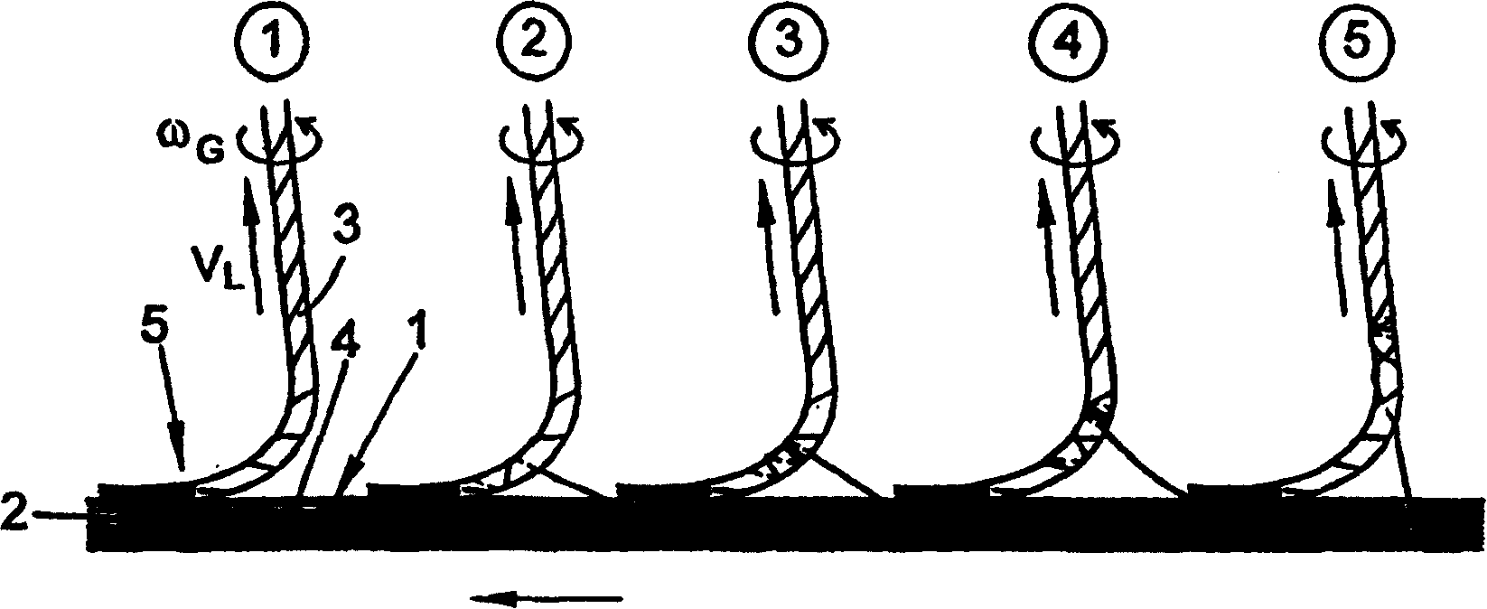
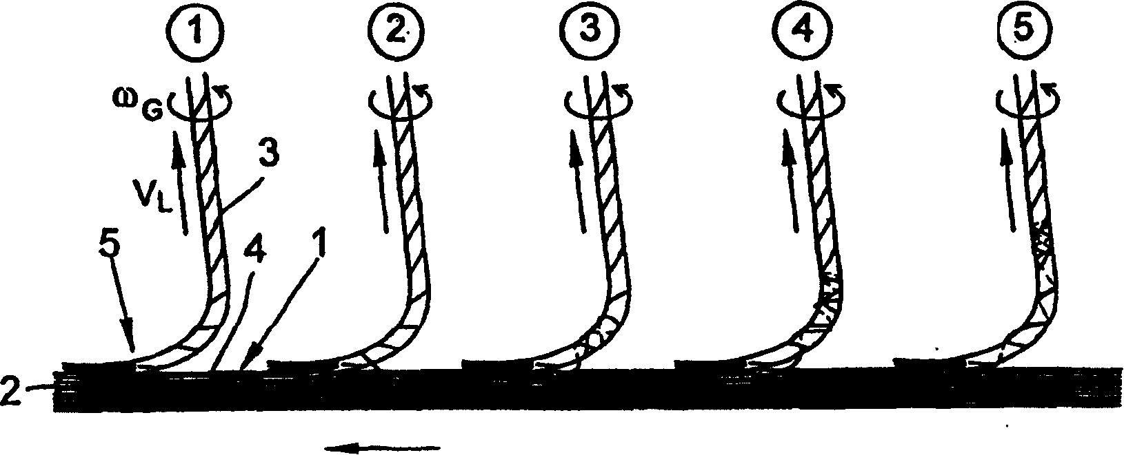
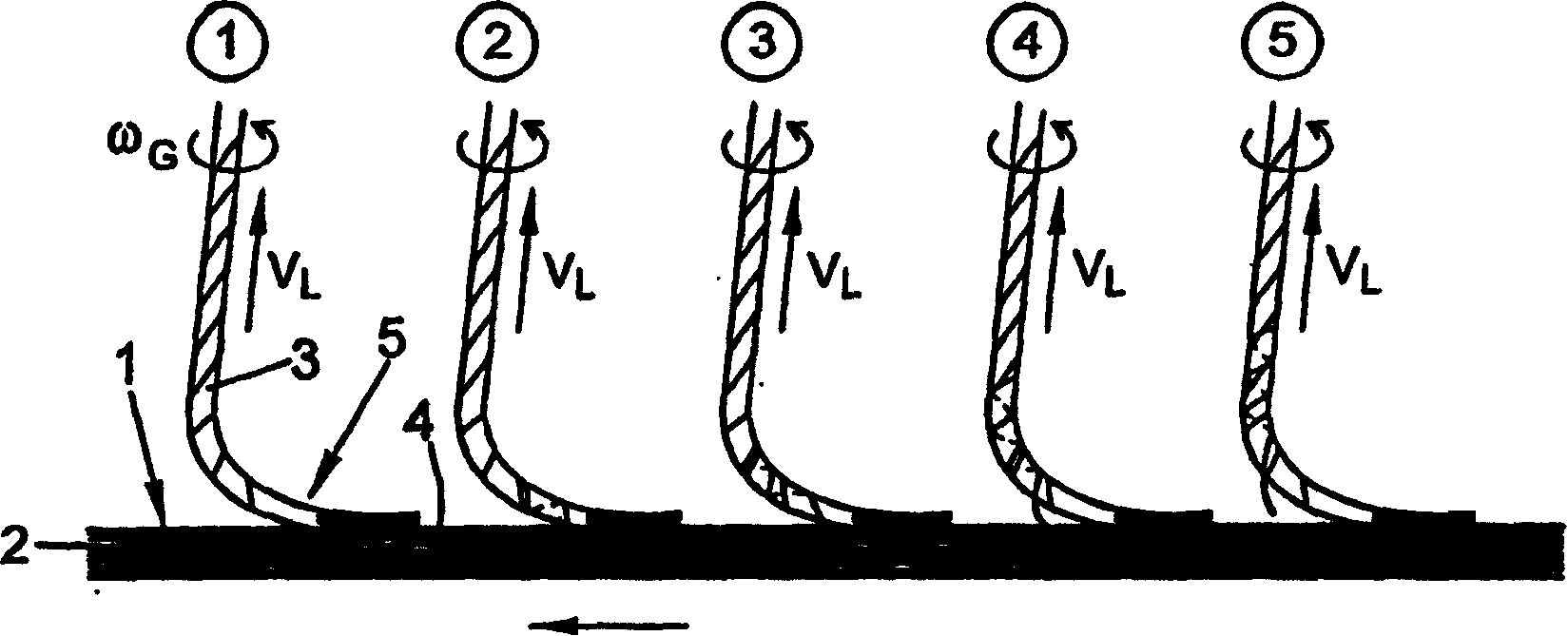
[0040] in Figure 1a , Shows the splicing stage of a single fiber 4 when spinning using the front access zone, that is, when the shank 3 is aligned with the spinning cup, and the single fiber 4 is caught by the yarn shank 3 at its front end. When entering zone 5, it reaches the rotor groove 1 from the fiber sliding surface 2 (the first stage). It can be clearly seen that in the yarn handle 3, the fiber turning direction is the Z twist direction. On the contrary, as can be seen in the second stage, the fiber 4 whose head is grasped is first wound around the outer layer of yarn in the S twist direction. As the doffing VL advances, the 4 ends of the fiber approach the point where other parts of the fiber are instantaneously wound around the outer layer of the yarn. In the fourth stage, the direction of the fiber 4 changes from S to Z, in which multiple concentrated turns may occur. Together, these loops bind the yarn and form so-called loops, which may interfere with subsequent proce...


PUM


Abstract

The object of the present invention is to provide an air spinning process in which at least the formation of wrapped fibers and in particular the formation of so-called “fiber loops” is significantly suppressed. According to the invention, the fiber flow from a fiber-guiding channel has a directional component in the rotor deflection so that the bobbin (3) extending from the yarn guide tube to the rotor groove is at least as far as the rotor groove (1 ) and bends opposite to the rotor rotation during spinning. Producing this yarn handle (3) bending direction is to realize in the yarn splicing process.

Description

Technical field [0001] The present invention relates to an air spinning method, in which fibers to be spun are fed into the spinning cup through a fiber guide channel and are collected in the spinning cup groove with the largest inner diameter of the spinning cup, and the fibers are rotated in a spinning cup through the rotation of the spinning cup. The so-called insertion zone is twisted into the yarn end and is led out as a finished yarn through a central yarn guide tube arranged approximately in a plane with a rotor groove. Background technique [0002] The development of air spinning can be traced back to a long time ago, and this method was only put into industrial application in the 1960s. Not only in the peripheral area, that is, in the peripheral area where the fiber sliver is transported, the single fiber is opened, the single fiber is sent to the spinning cup, and the fiber is drawn and wound, but also in the core area of ​​the fiber, that is, in the spinning cup Among ...

Claims


Application Information

Patent Timeline
IPC IPC(8): D01H4/08D01H4/50D01H4/24D02H1/00
CPCD01H4/24D01H4/50
Inventor J·梅耶尔M·拉斯曼
Owner OERLIKON TEXTILE GMBH & CO KG
Why Eureka
Try Eureka