Roll paper printer

A technology of printers and paper rolls, which is applied to printing devices, printing, and winding strips, etc., can solve the problems of reduced detection accuracy and achieve the effect of improving detection accuracy

Inactive Publication Date: 2007-02-14
SEIKO EPSON CORP
View PDF1 Cites 15 Cited by
  • Summary
  • Abstract
  • Description
  • Claims
  • Application Information

AI Technical Summary

Problems solved by technology

However, providing a taper with a large angle on the detection rod causes a problem of lowered detection accuracy because it is more difficult to set a point where the detection rod is accurately inserted into the roll paper core when the roll paper is reduced to a predetermined remaining volume than with a detection rod that does not have a taper. many
The same problem occurs with the mechanism that uses the detection rod to separate from the outer circumference of the roll paper

Method used


Image

  • Roll paper printer
  • Roll paper printer
  • Roll paper printer

Examples


no. 1 example

[0053] See below figure 1 A roll paper printer according to a first embodiment of the present invention is described through FIG. 8 .

[0054] * General configuration

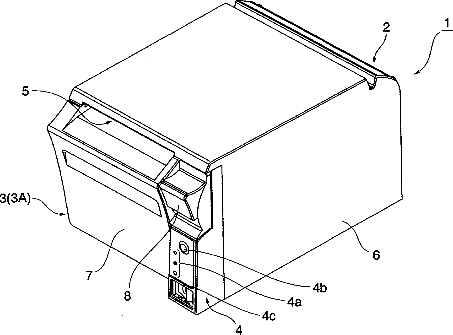
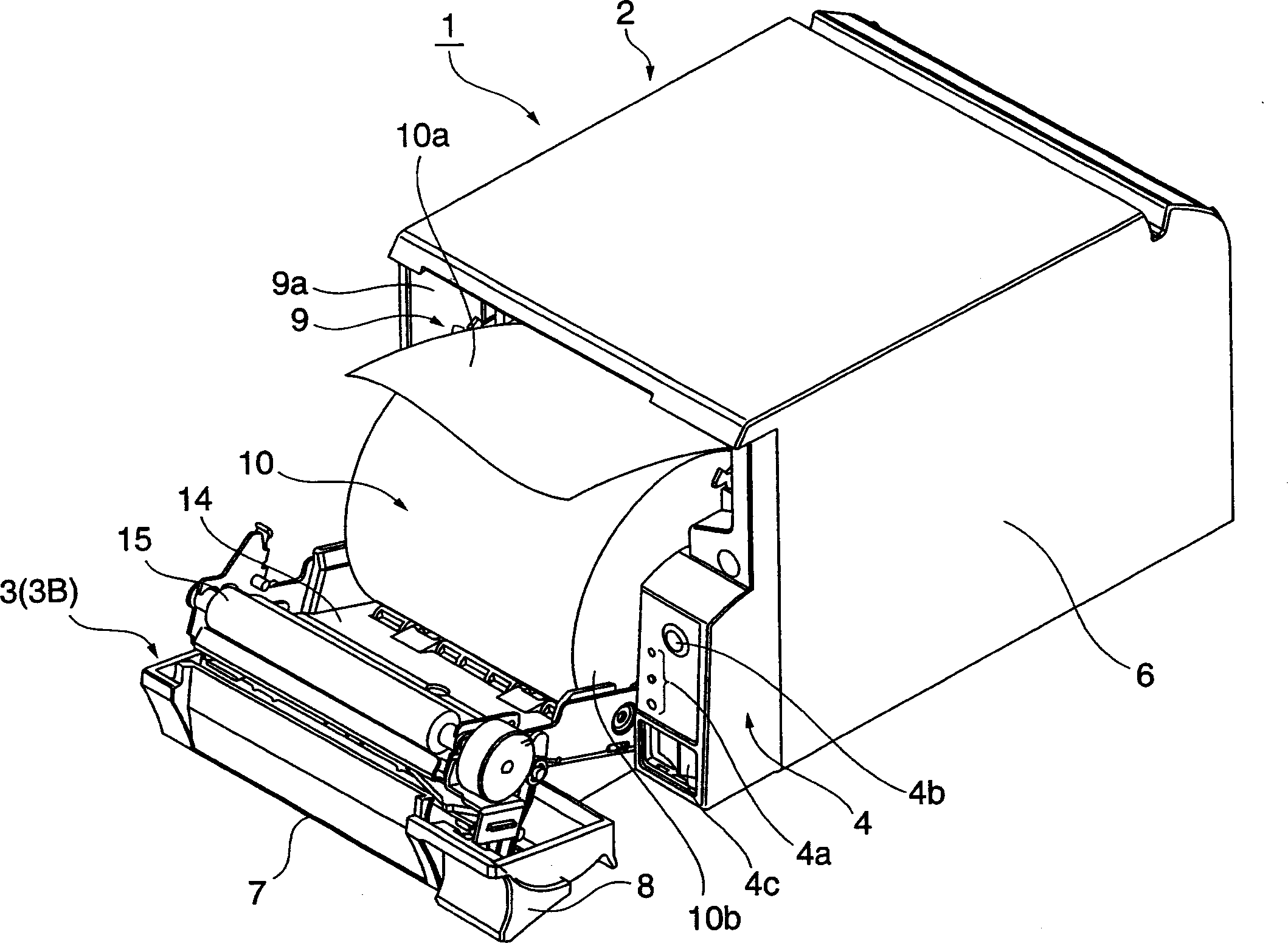
[0055] figure 1 is an external oblique view of the roll paper printer according to the present invention, and figure 2 It is a perspective view showing the roll paper printer when the operable cover is opened.

[0056] The roll paper printer 1 according to this embodiment of the present invention has a printer frame 2, and an operable cover unit 3 is attached to the front. An operation panel unit 4 is provided to a front corner of the printer chassis 2 . A paper outlet 5 extending in the printer width direction is formed at the top of the operable cover unit 3 in front of the printer.

[0057] The printer chassis 2 is covered by a box-shaped printer case 6 that is long in front and rear, and is opened on the front and bottom sides. An operable cover case 7 defining the front of the printer is attached to...

no. 2 example

[0097] See below Figure 9 to Figure 16 A roll paper printer of a second embodiment of the present invention will be described.

[0098] Figure 9 is an external oblique view of the roll paper printer, Figure 10 It is an oblique view of the mechanism part of the printer seen from the front left, Figure 11 It is a perspective view of the printer mechanism seen from the front right. Figure 12 is an oblique view of the printer mechanism with the operable cover unit open, and Figure 13 is a schematic diagram of the internal arrangement of a roll paper printer.

[0099] The roll paper printer 100 according to this embodiment of the present invention has a printer mechanism unit 200, a printer case 102 covering substantially the entirety of the printer mechanism unit 200, and an optional cover covering the front of the printer mechanism unit 200 that is not covered by the printer case 102. The cover case 103 is operated. A paper outlet 108 extending in the width direction ...


PUM


Abstract

A rolled sheet printer comprises a body unit and a closable cover unit mounted on the front face of a body unit closably to the front side. When the closable cover unit is opened, the front side of a rolled sheet storage part in a printer body is put into an opened condition to allow the replacement of the rolled sheet. A detecting protrusion of the rolled sheet detecting mechanism is protruded in the rolled sheet storage part. When the rolled sheet is running out, the position of its core hole lowers and the detecting protrusion is put into the core hole to detect that the rolled sheet is running out. When the closable cover unit is opened, a link lever is moved from a first position to a second position on the front side thereof and its abutting plate portion pushes the detecting protrusion therein to hold it in the condition being set out of the rolled sheet storage part. Thus, rolled sheet replacing work can be efficiently done without being disturbed by the detecting protrusion.

Description

technical field [0001] The present invention relates to a roll paper printer having a roll paper size detection device, the roll paper printer featuring an improvement enabling easy replacement of the roll paper. Background technique [0002] One type of roll paper printer has roll paper loaded such that the roll paper can simply be rolled on the bottom of the roll paper chamber. Roll paper generally has a long strip of recording paper wound into a roll around a hollow core with a hole in the center. Roll paper printers of this type also typically have roll paper size detection means for detecting the proximal end of the roll when a small amount of roll paper remains on the core. One type of roll paper size detection device has a rod inserted into a hole in a roll paper core. [0003] The lever is pressed against the round end (side) of the roll paper held by the push member at a predetermined height above the bottom of the roll paper chamber in the roll paper chamber. Wh...

Claims


Application Information

Patent Timeline
IPC IPC(8): B41J15/04B41J11/42B65H16/02B65H26/08
Inventor 前川博宜百濑次郎白鸟元良
Owner SEIKO EPSON CORP
Why Eureka
Try Eureka