Unlock instant, AI-driven research and patent intelligence for your innovation.

Air conditioner for vehicle

A technology for air conditioning devices and vehicles, which is applied to vehicle parts, transportation and packaging, air handling equipment, etc., can solve the problems of not considering the maintenance of expansion valve blocks, the installation of expansion valve blocks is not disclosed, and the expansion valve blocks cannot be taken out.

Inactive Publication Date: 2007-02-14
JAPAN CLIMATE SYSTEMS CORP
View PDF5 Cites 2 Cited by
  • Summary
  • Abstract
  • Description
  • Claims
  • Application Information

AI Technical Summary

Problems solved by technology

[0014] As mentioned above, in the existing technology, when maintaining the expansion valve block located on the front wall or side wall of the air conditioning unit, the expansion valve block cannot be simply taken out.
That is, without taking out the air supply unit and the air conditioning unit from the vehicle body, only the expansion valve block cannot be taken out, and maintenance of such an expansion valve block is not considered at all.
[0015] In addition, the following technology has been disclosed: when replacing the evaporator as a cooling heat exchanger, in order not to take the air conditioning unit out of the car, a part of the air conditioning box is provided as a cover member, and the cover member is removed to remove the evaporator. take out the evaporator, as described in Japanese Patent Laid-Open No. 10-81123, but in this case, where the expansion valve block is arranged at the end of the evaporator, and how to take it out etc., and the installation of the expansion valve block has not been made public

Method used


Image

  • Air conditioner for vehicle
  • Air conditioner for vehicle
  • Air conditioner for vehicle

Examples


Embodiment Construction

[0096] Embodiments of the present invention will be described below with reference to the drawings.

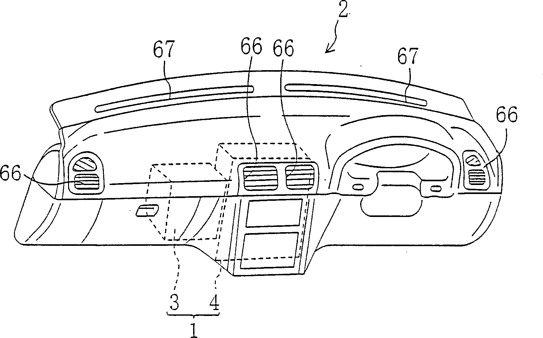
[0097] figure 1 It shows the state where the air conditioner of this invention is arrange|positioned in a vehicle. The air conditioner 1 is housed inside an instrument panel 2 provided in the interior of an automobile. The car is respectively provided with a driver's seat and an assistant's seat on the right side and the left side of the car body, the so-called right-hand drive car, and the front engine room and the front side of the car room are covered by the buffer panel D (only on the front side of the car body). image 3 Indicated in) separated. In addition, in the present embodiment, the vehicle body front side and the vehicle body rear side of the air conditioner 1 are simply referred to as the front side and the rear side, respectively.

[0098] figure 2 It is a schematic diagram of the appearance of the air conditioner 1 in the embodiment of the present invention...


PUM


Abstract

The invention relates to an air conditioner (1), in which air introduced into an air conditioning unit (4) flows through an evaporator (30) and a heater core (31) disposed in the unit (4) respectively, an expansion valve block (33) disposed at a side wall of the air conditioning unit (4) is disposed directly at the side wall of the air conditioning case (20) that is located at driver-seat side resulting in easy and efficient operations for installment / removal of the expansion valve block (33).

Description

[0001] This divisional application is a divisional application of the following application: [0002] Application number: 02146299.2; [0003] Application date: October 21, 2002; [0004] Applicant: Japan Air Conditioning System Co., Ltd.; [0005] Invention name: Vehicle air conditioner technical field [0006] The present invention relates to a vehicle air conditioner, and particularly relates to the design and structure of an expansion valve of a cooling heat exchanger provided in an air conditioner unit. Background technique [0007] So far, the following technology has been disclosed in Japanese Patent Application Laid-Open No. 2000-25447 regarding this type of vehicle air-conditioning device: an air-conditioning unit is arranged near the center in the vehicle body width direction in the instrument panel, and an air-conditioning unit is arranged in the passenger seat A blower unit is installed on one side, and a heat exchanger for cooling and a heat exchanger for hea...

Claims


Application Information

Patent Timeline
IPC IPC(8): B60H1/32
Inventor 前坊友纪米原真司山本和弘山本努桑原武司福冈史成伯方俊树冈本忠
Owner JAPAN CLIMATE SYSTEMS CORP