
Intelligent method for detecting antenna fault

A fault detection and smart antenna technology, applied in antenna radiation patterns, measurement devices, measurement of electrical variables, etc., can solve problems such as affecting the call quality of users covered by cell coverage, and achieve the effect of accurate measurement and simple calculation

Inactive Publication Date: 2007-02-14
江苏海湾电气科技有限公司
View PDF0 Cites 45 Cited by
  • Summary
  • Abstract
  • Description
  • Claims
  • Application Information

AI Technical Summary

Problems solved by technology

However, when one or several elements of the smart antenna fail, it will directly affect the coverage of the cell and the user's call quality

Method used


Image

  • Intelligent method for detecting antenna fault
  • Intelligent method for detecting antenna fault
  • Intelligent method for detecting antenna fault

Examples


Embodiment Construction

[0025] Various preferred embodiments of the present invention will be described in detail below in conjunction with the accompanying drawings.

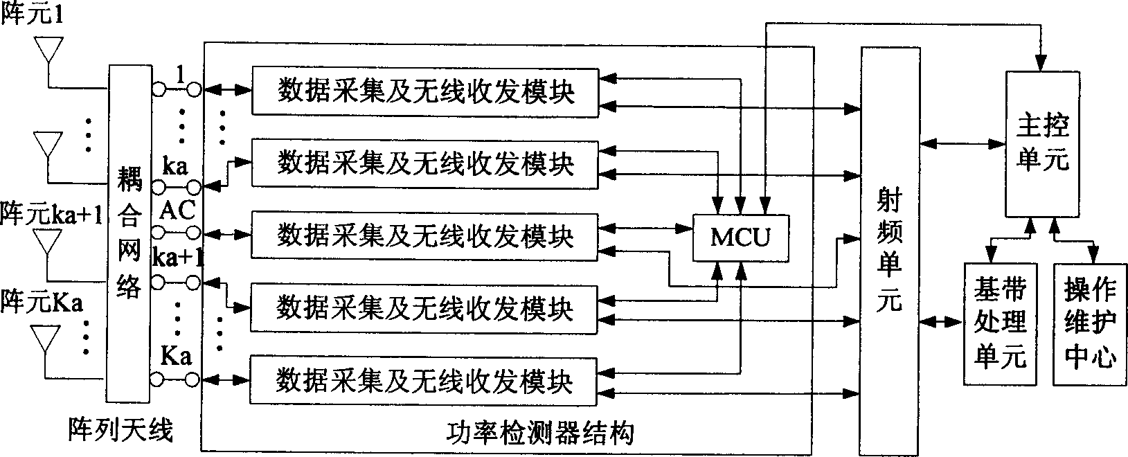
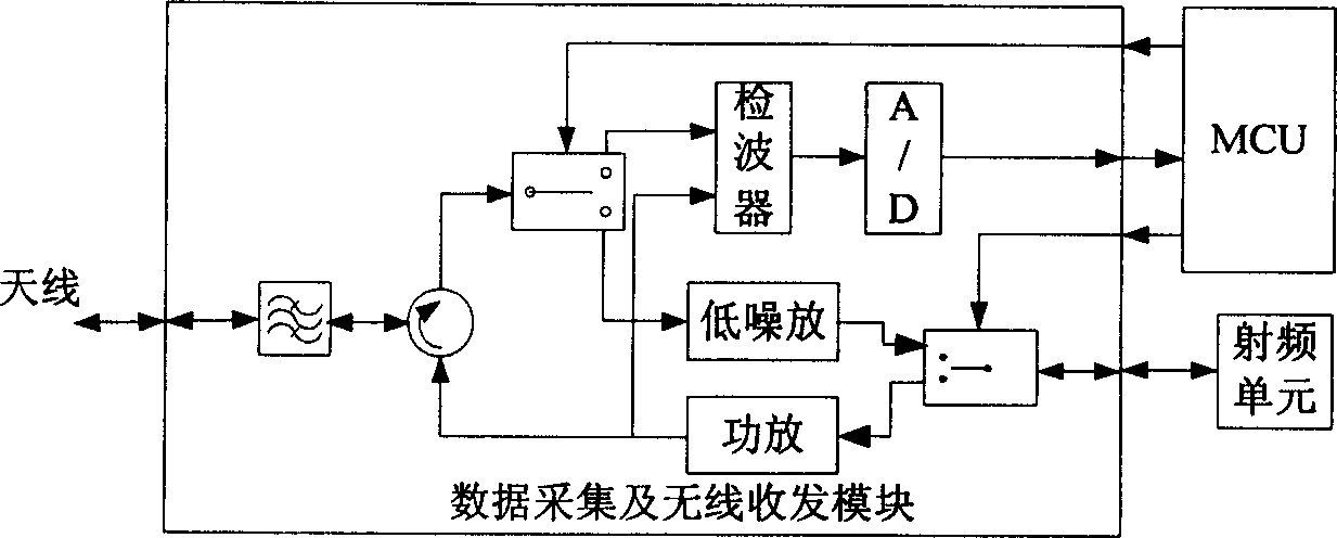
[0026] The method for detecting the failure of the smart antenna array element according to the present invention, such as figure 1 As shown, the device includes the following parts: a smart antenna; a power detection device for detecting the power of the transmitted and received signals; a main control unit for controlling the operation of the entire base station system and detecting antenna faults; for base station radio frequency signal Radio frequency unit for transceiver; baseband processing unit for baseband signal processing; operation and maintenance center for base station maintenance and alarm display.

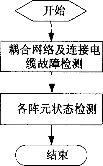
[0027] The method for detecting failure of a smart antenna array element according to the present invention comprises the following steps:

[0028] The first step is to set the transmit and receive switches of all antenna c...


PUM


Abstract

This invention relates to a method for testing intelligent antenna faults including: setting the TR switches of all antenna channels a receiving mode and that of the correcting channel a transmission mode, in which, the correcting antenna sends down-line signals to judge if the coupled network and feed lines connecting the array elements are normal by the tested emission signal power of the correcting antenna and the receiving signal power of the array element of the antennas, then to detect if the antenna element of the normal test state is disabled, which judges if the power defference of the measured receiving signal and emission signal is less than a throshld value designed by a fixed coupled relation to get the test result of the fault of intelligent antennas.

Description

technical field [0001] The invention relates to a fault detection method for a smart antenna by a base station adopting smart antenna technology in the communication field. Background technique [0002] The existing smart antenna technology is a new technology that is getting more and more attention in the field of mobile communication. Especially in the TDD working mode, the uplink and downlink channels use the same carrier frequency, so it can be considered that the uplink and downlink channels of the same user are completely symmetrical. , which is conducive to the use of smart antenna technology. [0003] The smart antenna can adaptively adjust the direction of the beam according to the change of the user's position, so that the received power of the desired user is maximized, and at the same time, the interference of the undesired user is reduced, so as to achieve the purpose of improving the system capacity. However, when one or several elements of the smart antenna f...

Claims


Application Information

Patent Timeline
Patent Type & Authority Applications(China)
IPC IPC(8): H04B17/00H04B7/00G01R29/00G01R29/10
Inventor 卢勤博曾召华秦洪峰华海宁
Owner 江苏海湾电气科技有限公司
Features
  • Generate Ideas
  • Intellectual Property
  • Life Sciences
  • Materials
  • Tech Scout
  • Unparalleled Data Quality
  • Higher Quality Content
  • 60% Fewer Hallucinations
Learn More