Forming machine for screw thread

A forming machine and threading technology, which is applied to other household appliances, household appliances, applications, etc., can solve the problems of use restrictions, restricting large-scale processing and production of threading, and achieve the effects of improved mechanization, compact structure, and convenient processing and assembly.

Inactive Publication Date: 2007-02-21
HEBEI UNIVERSITY OF SCIENCE AND TECHNOLOGY
View PDF0 Cites 4 Cited by
  • Summary
  • Abstract
  • Description
  • Claims
  • Application Information

AI Technical Summary

Problems solved by technology

At present, due to the lack of suitable forming and processing facilities, the large-scale processing and production of this kind of thread is restricted, and its use is also limited.

Method used


Image

  • Forming machine for screw thread
  • Forming machine for screw thread
  • Forming machine for screw thread

Examples


Embodiment Construction

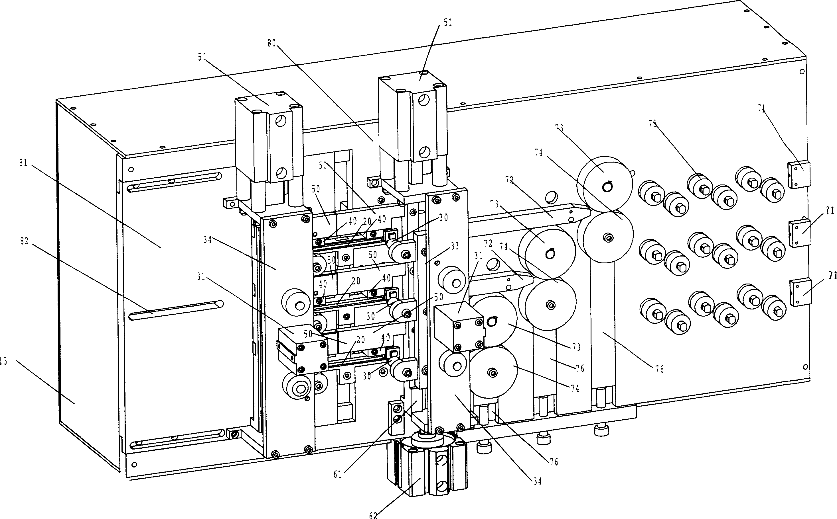
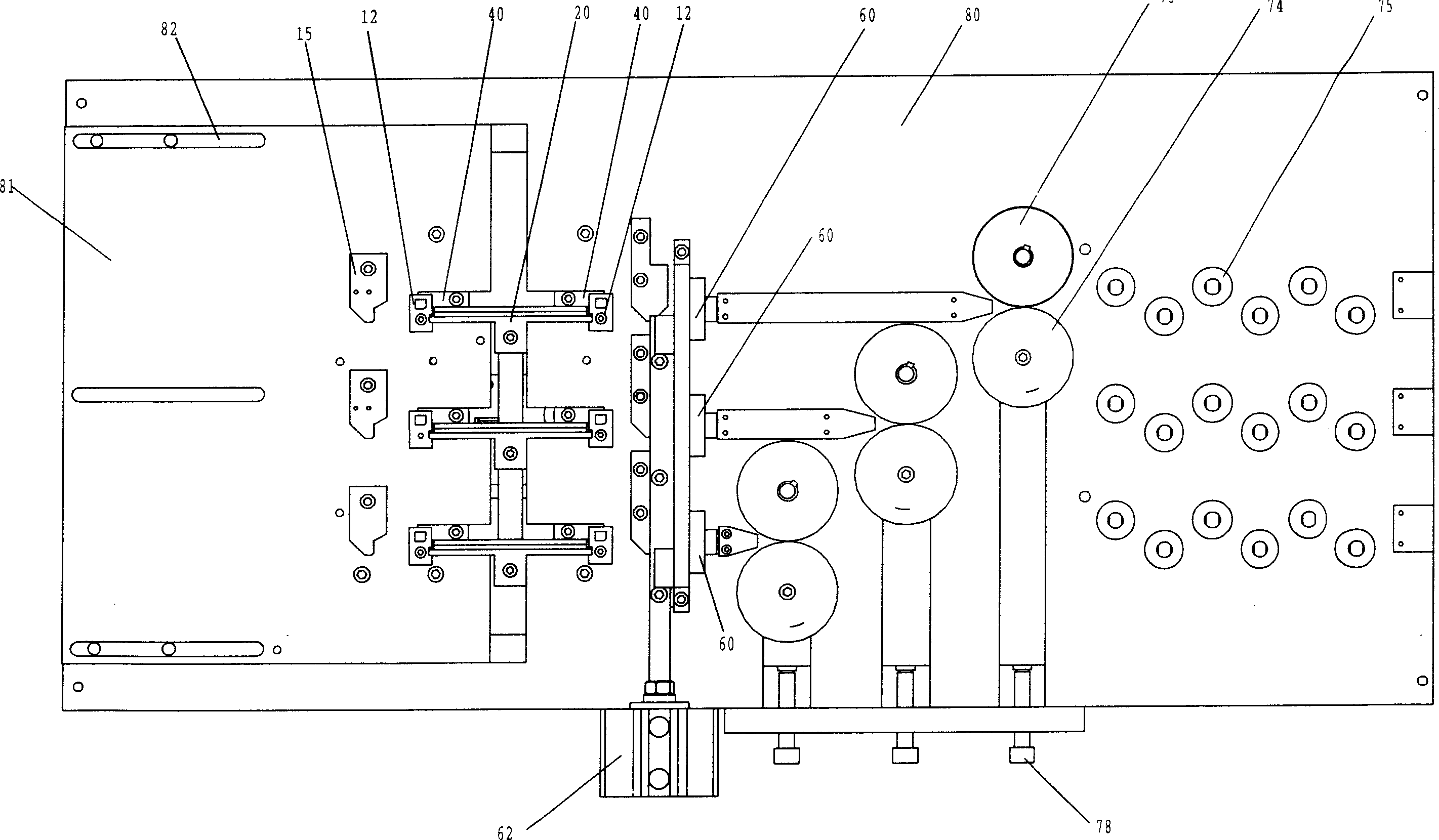
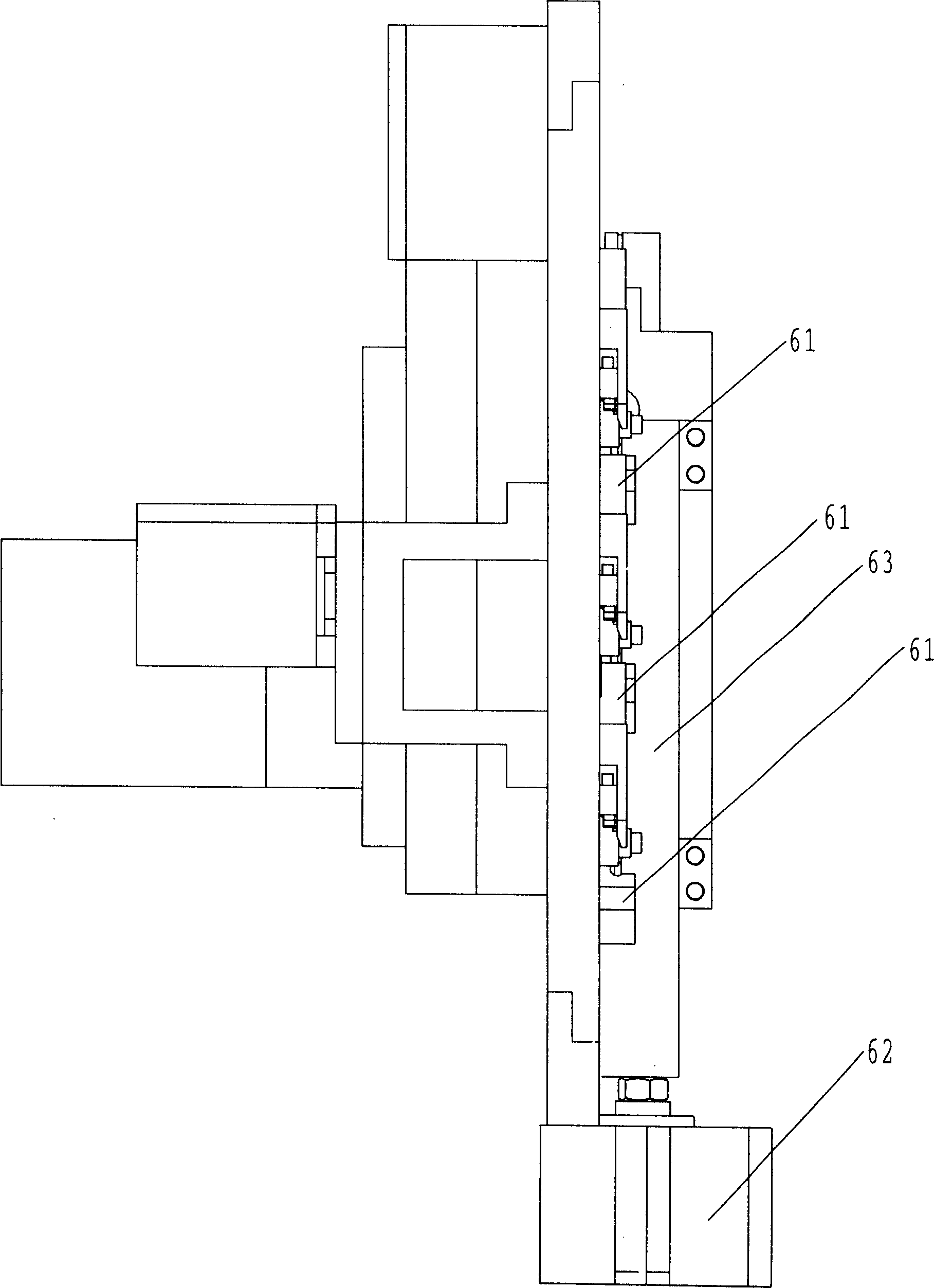
[0044] refer to figure 1 , 2, 3, 4, 5, 6, 7, 8, 9, 10, 11, 12, 13. The most basic structural form of the present invention can be made of a set of wire bending head, rotary drive, wire guide, fastening, preliminary forming, final forming and wire cutting mechanism. At this time, the symmetrically arranged wire bending heads 12 and the rotating drive mechanism are arranged along the plate surface of the plate frame 13 . The wire guide plate telescopic cylinder 21 in the wire guide mechanism is horizontally arranged on the back side of the plate frame 13, and its piston rod is connected with the wire guide plate 20 between the symmetrical wire bending heads 12. The pressure head telescopic cylinder 31 in the clamping mechanism is horizontally placed on figure 1 , 2 The front of middle plate type frame 13, the piston rod 35 ( Figure 13 Middle) is connected with the pressure head 30. Two primary forming push pedals 40 in the primary forming mechanism are symmetrically pos...


PUM


Abstract

A machine for manufacturing the fastening wire used as binding part is composed of machine frame, wire bending unit with symmetrically arranged wire bending head and rotation driver, wire guider, fastening unit, primary shaping unit, final shaping unit, and the telescopic cylinder matched with the push press plates used by the last 4 units for bending by 270 degrees and horizontal and vertical 90 degrees.

Description

technical field [0001] The invention relates to thread forming processing facilities and belongs to the technical field of thread production facilities. Background technique [0002] Figure 11 The buckle shown is a binding piece that has been used in recent years to build the steel skeleton of building concrete components and garbage bags. Using this piece can easily and quickly form a tight and not easy to loosen binding head, so it is favored by construction and other industries. There is a broad market prospect. [0003] as Figure 11 As shown, this bundle has a special shape, and its two ends need to be bent 270° and then folded back. At present, due to the lack of suitable forming and processing facilities, the large-scale processing and production of this kind of button thread is restricted, and its use is also limited. Research and development of wire forming processing facilities has become a top priority. Contents of the invention [0004] The technical proble...

Claims


Application Information

Patent Timeline
Patent Type & Authority Applications(China)
IPC IPC(8): B21F45/16B21F1/00B21F23/00B21F11/00
Inventor 张嘉钰单根立刘文学商国娟齐习娟刘跃辉
Owner HEBEI UNIVERSITY OF SCIENCE AND TECHNOLOGY
Why Eureka
Try Eureka